


Factory Service Manual For Komatsu Engine For Komatsu Forklift Truck. Manual Contains Illustrations, Instructions, Diagrams For Step By Step Remove And Install, Assembly And Disassembly, Service, Inspection, Repair, Troubleshooting, Tune-Ups.
Format: PDF
Language: English
Pages: 228
Number: SM127
Wiring Diagrams: Yes
Model
Komatsu Engine
TB45E
SN 064005 And Up
Contents
-FEDERAL EPA EMISSION CONTROL STATEMENT FOR OFF-ROAD LSI (NON-DIESEL) ENGINES (TB45E ENGINES)
Labels Required And Label Locations
Warranty
-ENGINE GENERAL
Precautions For Safety And Quality
How To Use This Manual
Trouble Shooting
ECM General Service Information
Precautions
Preparation
Service Data
-ENGINE TUNE-UP
Valve Clearance
Engine Drive Belt
Engine Oil
Compression Pressure
Spark Plug
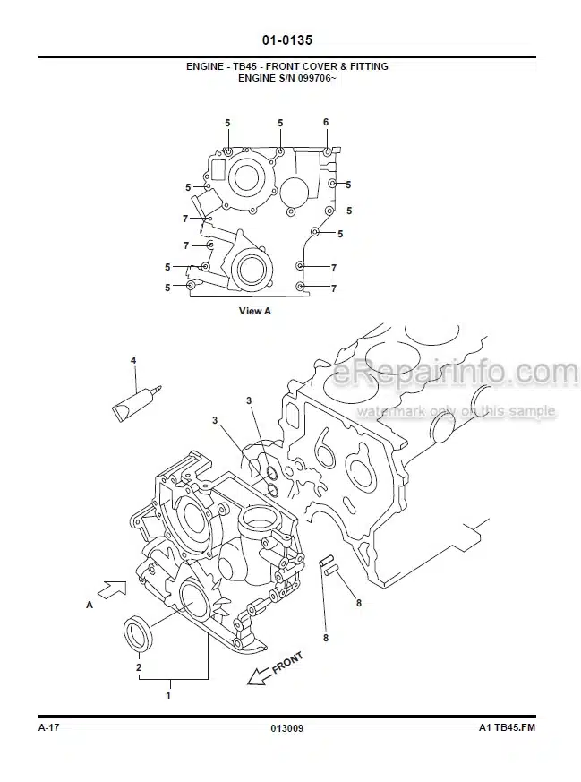
-ENGINE MECHANICAL
Intake Manifold
Exhaust Manifold
Oil Pan And Strainer
Rocker Cover
Rocker Arm And Rocker Shaft Assembly
Cylinder Head
Timing Chain
Removal And Installation Of Engine
Cylinder Block
-ENGINE LUBRICATION
Oil Pump
-ENGINE COOLING SYSTEM
Changing Engine Coolant
Water Pump
Thermostat
-TB45 ENGINE CONTROL
Precautions
Preparation
Engine Control System
System Diagram -Gasoline
Basic Inspection
Troubleshooting
-TB45 ENGINE CONTROL
Power Supply And Ground System
Crankshaft Position Sensor 1 Degree (POS)
Crankshaft Position Sensor 120 Degree (Ref) Signal Circuit
Mass Air Flow Sensor System
Engine Coolant Temperature Sensor System
Heated Oxygen Sensor System
Vehicle Speed Sensor System
Throttle Position Sensor System
Accelerator Pedal Position Sensor System
Accelerator Pedal Position Sensor / Intake Air Temperature
PNP Switch System
Stop Lamp Switch System
Electric Load Switch System
Ignition System
Fuel Injector System
Fuel Pump System
Engine Warning Light System
Heated Oxygen Sensor Heater System
LPG Injector System
Throttle Control Motor System
LPG Fuel Pressure Sensor System
LPG Assistance Injector System
Blowby Gas Restoration Device
Fuel Cut Function
Removal And Installation Of ECCS Components
Service Data And Specifications (SDS)
-ENGINE FUEL SYSTEM
Description
Disassembly And Reassembly Of LPG System
-ENGINE ELECTRICAL SYSTEM
Starting System
Charging System
-MAINTENANCE SCHEDULE CHART
First Month Or Initial 200 Hours Of Service
Every 2 Weeks Or 100 Hours Of Service
Every Month Or Every 200 Hours Of Service
Every 3 Months Or Every 600 Hours Of Service
Every 6 Months Or 1.200 Hours Of Service
Every 2,000 Hours Of Service
Every 12 Months Or 2,400 Hours Of Service
Every 18 Months Or 3,600 Hours Of Service
What you get
You will receive PDF file with high-quality manual on your email immediately after the payment.


Reviews
There are no reviews yet.