


Factory Shop Manual For Komatsu Wheel Loader. Manual Contains Illustrations, Instructions, Diagrams For Step By Step Remove And Install, Assembly And Disassembly, Service, Inspection, Repair, Troubleshooting, Tune-Ups.
Format: PDF
Language: English
Pages: 1166
Number: SEBM025405 (march 2005)
Bookmarks: Yes
Searchable: Yes
Wiring Diagrams: Yes
Hydraulic Diagrams: Yes
Model
Komatsu Wheel Loader
WA430-5
Serial No. 60001 and up
Contents
-GENERAL
General Assembly Drawing
Specifications
Weight Table
List Of Lubricant And Coolant
-STRUCTURE AND FUNCTION,MAINTENANCE STANDARD
Cooling System
Engine Mount, Transmission Mount
Power Train
Power Train System Diagram
Drive Shaft (Propeller Shaft)
Torque Converter,Transmission Piping
Torque Converter
Transmission
Transmission Control Valve
Axle
Differential
Final Drive
Axle Mounting,Center Hinge Pin
Steering Piping
Steering Column,Orbit-Roll
Steering Valve
Orbit-Roll Valve
Stop Valve
Steering Pump, Switch Pump
Emergency Steering Pump(OP)
Emergency Steering Motor(OP)
Steering Cylinder
Joystick Steering Lever (OP)
Steering Lever (OP)
Steering Switch Valve (OP)
Brake Piping
Brake Valve
Charge Valve
Accumulator (For Brake)
Brake
Parking Brake Control
Parking Brake
Parking Brake Solenoid Valve
Parking Brake Emergency Release Valve
Hydraulic Piping
Work Equipment Control Lever
Hydraulic Tank
Torque Converter Charging,Work Equipment,And Pilot Control Pumps
PPC Relief Valve
E.S.S.S .Valve (OP)
Work Equipment Control Valve
Work Equipment PPC Valve
PPC Valve (For Multi Function Mono Lever)
Operation
EPC Solenoid Valve(OP)
Shut Off Valve (OP)
Attachment PPC Valve(OP)
Cooling Fan Motor
Cooling Fan Motor Drive Pump
Work Equipment Linkage
Bucket
Bucket Positioner,Lift Arm Kick-Out
Work Equipment Cylinder
Cab
Air Conditioner (OP)
Machine Monitoring System
Machine Monitor
Transmission Control System
Transmission Controller
Work Equipment Control System (OP)
Work Equipment Controller
Electric Transmission Control
Kick Down,Hold Switch
Engine Starting Circuit
Engine Stop Circuit
Preheating Circuit
Engine Power Mode Selector Circuit
Parking Brake Circuit
Sensors
-TESTING AND ADJUSTING
Testing And Adjusting Data
Standard Value Table For Chassis
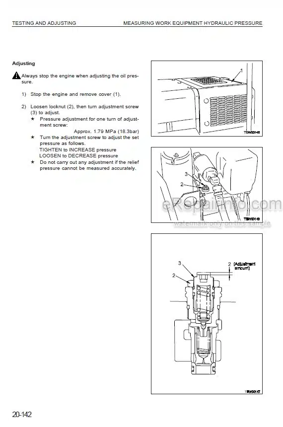
Testing And Adjusting
Troubleshooting
-DISASSEMBLY AND ASSEMBLY
Precautions When Performing Operation
Special Tool List
Removal And Installation Of Fuel Injection Pump Assembly
Removal And Installation Of Nozzle Holder Assembly
Removal And Installation Of Cylinder Head Assembly
Removal And Installation Of Engine Assembly
Removal And Installation Of After Cooler Assembly
Removal And Installation Of Radiator, Fan Motor And After Cooler Assembly
Removal And Installation Fuel Tank Assembly
Removal And Installation Of Parking Brake Disc And Plate
Removal And Installation Of Torque Converter And Transmission Assembly
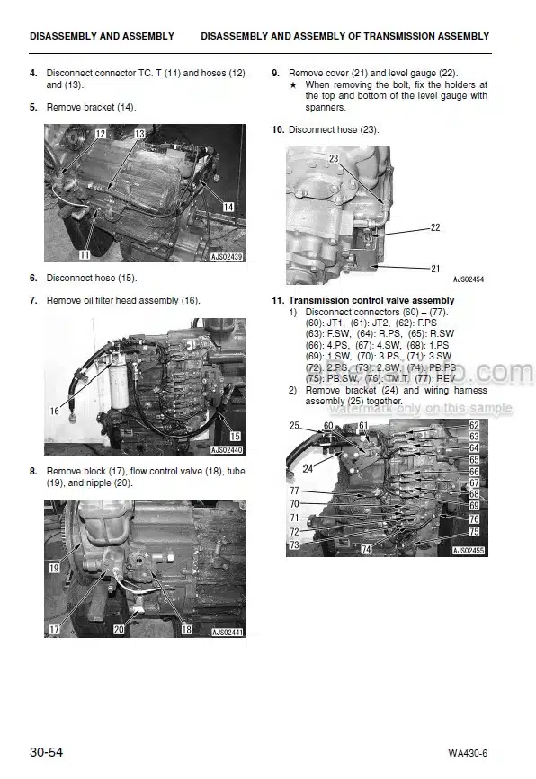
Disassembly And Assembly Of Transmission Assembly
Disassembly And Assembly Of Transmission Clutch Pack Assembly
Disassembly And Assembly Of Parking Brake Assembly
Disassembly And Assembly Of Torque Converter Assembly (Standard Specification)
Disassembly And Assembly Of Torque Converter Assembly(Lock-Up Specification)
Removal And Installation Of Front Axle Assembly
Removal And Installation Of Rear Axle Assembly
Disassembly And Assembly Of Axle Housing Assembly
Disassembly And Assembly Of Differential Assembly
Removal And Installation Of Center Hing Pin
Removal And Installation Of Cab Assembly
Removal And Installation Of Cab And Floor Frame Assembly
Removal And Installation Of Operator’s Cab Glass (Stuck Glass)
Removal And Installation Of Torque Converter Work Equipment And Pilot Control Pump Assembly
Removal And Installation Of Steering, Switch And Fan Pump Assembly
Removal And Installation Of Steering Demand Valve Assembly
Removal And Installation Of Travel Dumper Valve Assembly
Removal And Installation Of Work Equipment Valve Assembly
Removal And Installation Of Hydraulic Tank
Removal And Installation Of Hydraulic Tank
Disassembly Ad Assembly Of Hydraulic Cylinder
Removal And Installation Of Counter Weight
Removal And Installation Of Air Conditioner Unit
Removal And Installation Of Air Conditioner Compressor Assembly
Disassembly, Assembly Of Operator’s Seat Assembly
-OTHERS
Power Train Oil Circuit Diagram (Without Torque Converter Lockup Clutch)
Power Train Oil Circuit Diagram(With Torque Converter Lockup Clutch)
Brake Oil Circuit Diagram
Work Equipment Hydraulic Circuit Diagram
Work Equipment Hydraulic Circuit Diagram (For Electric Work Equipment Lever)
Electrical Circuit Diagram
What you get
You will receive PDF file with high-quality manual on your email immediately after the payment.


Reviews
There are no reviews yet