


Factory Shop Manual For Komatsu Wheel Loader. Manual Contains Illustrations, Instructions, Diagrams For Step By Step Remove And Install, Assembly And Disassembly, Service, Inspection, Repair, Troubleshooting, Tune-Ups.
Format: PDF
Language: English
Pages: 306
Number: VEBM250100 (may 2005)
Bookmarks: Yes
Searchable: Yes
Wiring Diagrams: Yes
Hydraulic Diagrams: Yes
Model
Komatsu Wheel Loader
WA65-5
SN H50051 And Up
WA70-5
SN H50051 And Up
WA80-5
SN H50051 And Up
Contents
-SAFETY
Safety Notice
Foreword
How To Read The Shop Manual
Hoisting Instructions
-GENERAL
Dimensions, Weights And Operating Data WA65-5
Specifications WA65-5
Weight Table WA65-5
Dimensions, Weights And Operating Data WA70-5
Specifications WA70-5
Weight Table WA70-5
Dimensions, Weights And Operating Data WA80-5
Specifications WA80-5
Weight Table WA80-5
Lubricants And Operating Mediums: WA65-5/ WA70-5
Lubricants And Operating Mediums: WA80-5
Basic Procedures Of Maintenance
Torque List – Screws And Nuts
-STRUCTURE AND FUNCTION
Powertrain
Closed Circuit
Hydraulic Drive System 20Km/H
Hydraulic Drive System 30Km/H
Variable Displacement Pump
Variable Displacement Motor
Drive Shaft
Axle Mounting – Front Axle
Axle Mounting – Rear Axle
WA65-5 / WA70-5: Front Axle
WA80-5: Front Axle
Rear Axle With Transfer Box
Transfer Box Tb172
Limited Slip Differential (Locking Value 25%)
Locking Differential (Locking Value 100%)
Wheel Hub, Front And Rear Axle
WA65-5 / WA70-5: Service And Parking Brake, Front Axle
WA80-5: Service Brake, Front Axle
WA80-5: Parking Brake, Front Axle
Service And Parking Brake Circuit
Wa65-5 / Wa70-5: Service Brake Assembly
Wa80-5: Service Brake Assembly
Inch-Brake Valve
Steering Articulation Joint
Steering System
Work Equipment Hydraulic WA65/WA70-5
Work Equipment Hydraulic WA80-5
PPC Valve
Main Control Valve
WA65-5 / WA70-5: Lift Cylinder
WA80-5: Lift Cylinder
Dump Cylinder
Steering Cylinder
Lifting Frame With Quick-Coupler
Quick-Coupler
Monitor Display
Sensors
Ribbon Heater
Engine Stop / Start / Preheating Circuit
Electrical Fuses And Relays
Electrical Diagrams
Air Conditioner (Option)
-TESTING AND ADJUSTING
Standard Value Table For Engine
Standard Value Table For Chassis
Standard Value Table For Electrical Parts
Test Certificate
Valve Lash Clearance
Engine Compression Test
Injection Nozzle Pressure
Fuel Injection Timing
V-Belt Tension
Engine Rpm
Rpm-Dependent Drive Take-Up
Engine Stall Torque Rpm
Feed Pump (And Servo Oil Pressure For WA80-5)
Hydraulic Pressure Cut-Off
Working Hydraulic Pressure
Steering Oil Pressure
Operating Time For Steering Wheel
Operating Force Of Steering Wheel
Disc Brake (Foot Brake WA80-5)
Brake (WA65-5 And WA70-5)
Inch Valve – Basic Adjustment
Brake Efficiency
Parking Brake Efficiency
Travel Speed
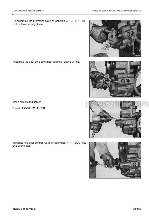
-DISASSEMBLY AND ASSEMBLY
Comments
Starter Assembly
Alternator Assembly
Water Pump Assembly
Engine Cover Assembly
Engine Cover Support Assembly
Engine Assembly
Clutch Assembly
Radiator Assembly
Fan Assembly
Inch Brake Valve Assembly
Priority Valve Assembly
Orbit-Roll-Valve Assembly
Counterweight Assembly
Control Valve Assembly
Main Control Valve Assembly
Pilot Valve Assembly
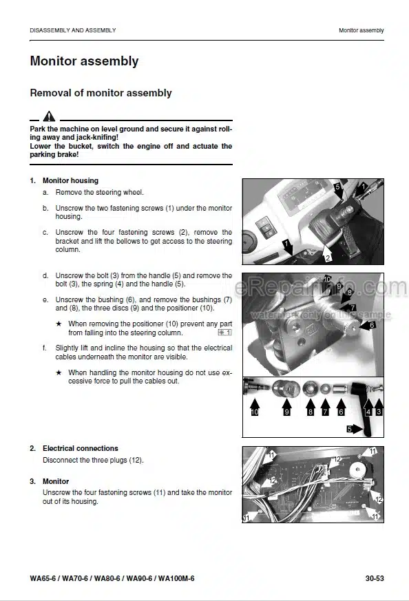
Monitor Assembly
Articulated Joint Assembly
Variable Motor Assembly
Rear Axle Assembly
Front Axle Assembly
Front Axle
Brake Caliper
Rear Axle
Variable Displacement Pump Assembly
Hydraulic Pump Assemblies
Quick-Attach Coupler Assembly
Steering Cylinder Assembly
Lift Cylinder Assembly
Dump Cylinder Assembly
Replacing Windows In Driver’s Cab
-OTHERS
Wiring Diagram
Wiring Diagram, Speed Control
Wiring Diagram, Immobilizer
Hydraulic Circuit Diagram
What you get
You will receive PDF file with high-quality manual on your email immediately after the payment.


Reviews
There are no reviews yet