


Factory Shop Manual For Komatsu Telescopic Handler. Manual Contains Illustrations, Instructions, Diagrams For Step By Step Remove And Install, Assembly And Disassembly, Service, Inspection, Repair, Troubleshooting, Tune-Ups.
Format: PDF
Language: English
Pages: 516
Number: WEBM005700 (issued 2005)
Bookmarks: Yes
Searchable: Yes
Wiring Diagrams: Yes
Hydraulic Diagrams: Yes
Model
Komatsu Telescopic Handler
WH609-1
SN 395F60001 And Up
WH613-1
SN 395FG0003 And Up
WH713-1
SN 395F70001 And Up
WH714-1
SN 395F70002 And Up
WH714H-1
SN 395F70003 And Up
WH716-1
SN 395F70004 And Up
Contents
SAFETY
FOREWORD
HOW TO READ THE SHOP MANUAL
HOISTING INSTRUCTIONS
STANDARD TIGHTENING TORQUE
COATING MATERIALS
ELECTRIC
WEIGHT TABLE
TABLE OF OIL AND COOLANT QUANTITIES
CONVERSION TABLE
-STRUCTURE AND FUNCTION
Engine-Transmission Coupling
Powertrain
Transmission
Front Axle
Rear Axle
Brake Pumps
Steering System (4Ws)
Steering Unit
Hydraulic Diagram
Hydraulic Pump
Control Valve
PPC Valve
Solenoid Valves
Safety Valves
Cylinders
Air Conditioning System
Climate Control System Operation
Electric Diagrams
-TESTING AND ADJUSTMENTS
Standard Specifications
Introduction
Valve Lash Adjustment
Checking Engine Speed
Tensioning The Air Conditioner Compressor Belt.
Adjusting Accelerator Cable Length
Adjusting Brake Pedal Travel And Positioning The Stop Lamp Microswitches
Adjusting The Parking Brakes
Bleeding Air From Circuits
Preparing The Machine Ready For Hydraulic Pressure Check And Calibration
Checking And Calibrating Work Equipment Hydraulic Pressures
Calibrating The Pressure Of The Steering System
Inspecting The Operation Of The Unloading Valve
Checking And Calibrating The DR Valve (Pump Flow Variation)
Checking The Dynamic Pump DP Value
Checking Pump Flow
Brake System Checks
Transmission (Power Shift) Checks
Transmission Assembly Pressure Checks
Checking The Speed Of The Transmission Shafts Responsible For Translation (Cardan Shafts)
Level Calibration
Checking Load Cell Calibration
Calibrating The Overturn Prevention System (SAR)
Checking Weight Percentage On Rear Axle
Checking Shoe Clearance
Checking Boom Side Alignment
Boom Chains
Chain Tensioning
Checking For Blow-By
Analysis Of The Causes Responsible For Hydraulic Drift
Equalizing Stabilizer Speed
Air Conditioning System Maintenance
Checking The A/C System’s Operating Temperature
-REMOVAL AND INSTALLATION
Precautions To Be Taken When Working
Special Tools
Engine Hood
Air Filter
Turbocompressor (Only If Equipped)
Exhaust Pipe
Generator – Fan Belt
Radiator-Exchanger Assembly
Muffler
Battery – Battery Tray
Cylinder Head
Injectors
Injection Pump
Hydraulic Pump
Complete Engine- Shift Assembly
Engine-Transmission
Control Valve Assembly
Bracket Control, Equipment Lock, And Frame Levelling Solenoid Valves
Air Conditioner Compressor (Only If Equipped)
Air Conditioner Compressor Belt
Servo-Control Feed Valve
Steering Selection Solenoid Valve Assembly
Front Axle
Rear Axle
Telescopic Boom
Lift And Offset Cylinders
Intermediate And Top Boom
Extension Cylinder
Boom Sliding Shoes
Extension And Retraction Chains (Versions With 3-Section Boom)
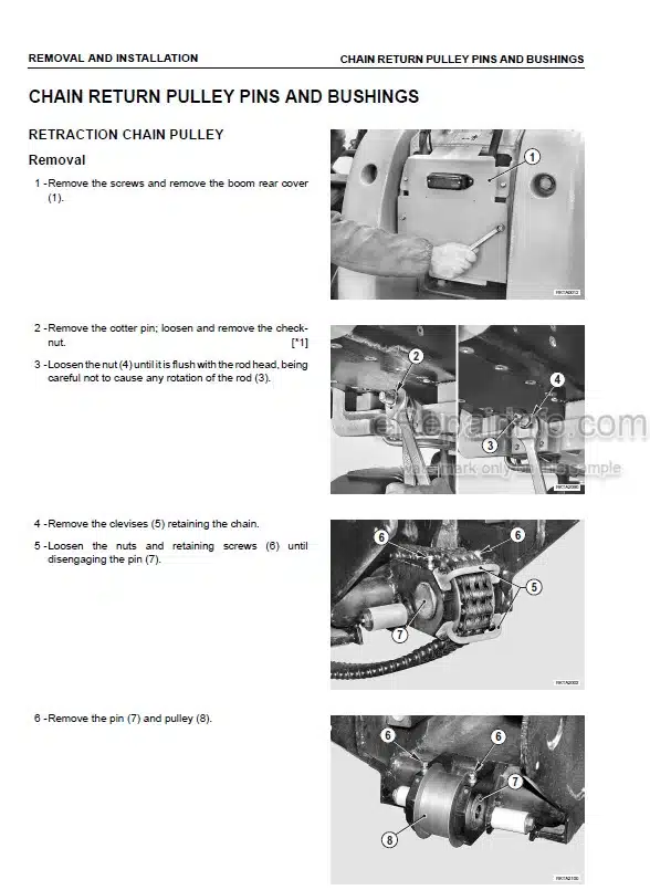
Chain Return Pulley Pins And Bushings
Load Cell
Control Unit
Ballast
Engine Line Centre
Accelerator Cable
Shift-Reversing Gear Lever Assembly
Steering Column Switch Unit – Dipswitch
Steering Unit
Steering Column
Brake Pumps
PPC Valve
Level
Wiper Motors
Parking Brake Cable
Dash / Instrument Panel
Control Panel
Fuse And Relay Centre
Propellershaft
Fuel Tank
Hydraulic Oil Tank
Frame Levelling Cylinder
Frame Swing Locking Rod (Wh609 And Wh613 Only)
Axle Locking Cylinder
Stabilizer Cylinders (If Equipped)
Equipment Holder
Equipment Motion Cylinder
Cylinders
Equipment Quick-Lock Assembly
Air Conditioner Fans
Air Conditioner Condenser Assembly
Dehumidifying Filter
Pair Conditioning System Pressure Switch
Cab
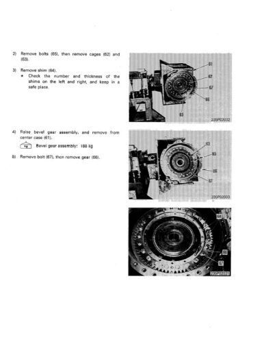
Transmission
Axles
-OTHERS
Cab Wiring
Electrical Diagram
What you get
You will receive PDF file with high-quality manual on your email immediately after the payment.


Reviews
There are no reviews yet.