Factory Service Manual For Liebherr Hydraulic Excavator. Manual Contains Illustrations, Instructions, Diagrams For Step By Step Remove And Install, Assembly And Disassembly, Service, Inspection, Repair, Troubleshooting, Tune-Ups.
Format: PDF
Language: English
Pages: 1806
Issued: november 1997
Bookmarks: Yes
Wiring Diagrams: Yes
Hydraulic Diagrams: Yes
Model
Liebherr Hydraulic Excavator
A900
A902
A912
A922
A932
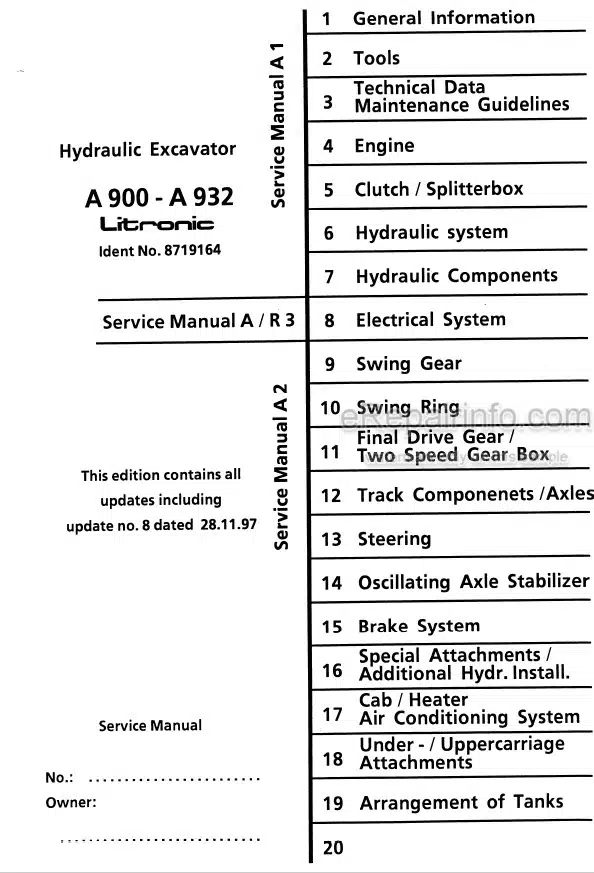
Contents
-GENERAL INFORMATION
Safety Guidelines
Charts/Norms
Repair welding
Service Fluids
Recommended List
-TOOLS
Special Tools for Excavator
Special Tools for Maintenance and Repair of Electrical Connections
Special Tools for Maintenance and Adjustment of Liebherr Diesel Engine
Special Tools for Maintenance and Adjustment of Deutz Diesel Engine
Spool Travel Measuring Tool
Leakage Plate
Piston Wrench
Impression fixture for SAT Swing Gear
Slotted – Nut Wrench for SAT Swing Gear
Filter Kid for Closed Swing Loop
-TECHNICAL DATA MAINTENANCE GUIDELINES
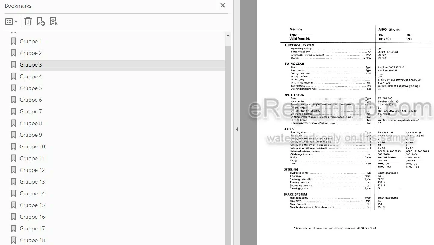
Technical Data
Maintenance Guidelines
-ENGINE
Technical Data
Engine Speed Adjustment
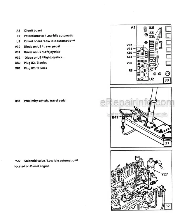
Sensor Controlled Low Idle Automatic
-CLUTCH / SPLITTERBOX
Coupling
Pump Distributor Gear
-HYDRAULIC SYSTEM
Operating Pressures – Hydraulic System
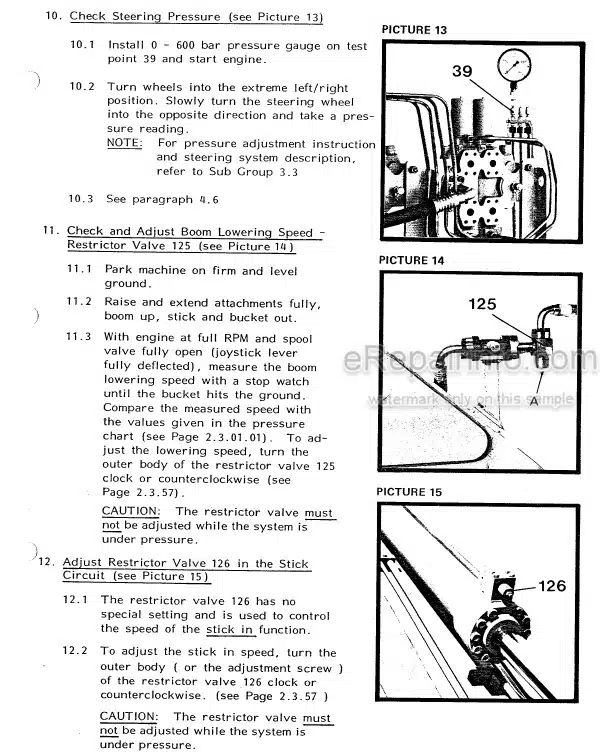
Pressure Check And Adjustments
Hydraulic System
-HYDRAULIC COMPONENTS
General Data / Variable Displacement Double Pump LPVD
Variable Displacement Double Pump LPVD
Swing Pump A4V
Pump Performance Curve
Hydraulic Motors /Types /
Hydraulic Fixed Displacement Motor FMF For Swing Drive
Hydraulic Fixed Displacement Motor FMF With Discharge
Hydraulic Variable Displacement Motor
Hydraulic Cylinder
Hydraulic Cylinder – Chart
Hydraulic Control
Control Unit
Distributor Block
Servo Control With Joystick
2- Way Servo Control With Foot Pedal / Hydr. Instal. Kit
1- Way Servo Control With Foot Pedal
Control Valve Blocks/-Chart
7- Way Control Valve Block
6- Way Control Valve Block
Added Control Valve Block
6 – Way Rotary Connection
5 And 7 Way Rotary Connection – Liebherr
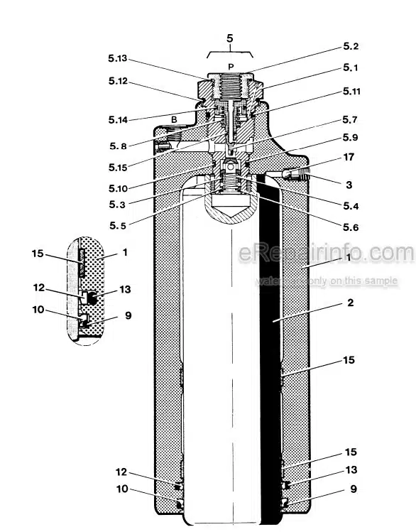
Primary Pressure Relief Valve – Pilot Operated
Pilot Operated Pr. Relief Valve W. Pressure Cut In
Pilot Operated Pr. Relief Valve W. Suction Function
Secondary Pressure Relief Valve Suction Valve
Suction Valve
Restrictor Check Valve
Load Holding Valve
-ELECTRICAL SYSTEM
Component Of Electrical System
Circuit Board A2 / 2
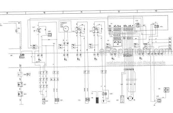
Electrical System – Basic Machine
Electrical System-Basic Machine
Electrical System – Basic Machine + Special Installations
Electrical System – Basic Machine ( Mit Glr)
Electrical System – Basic Machine (Mit Gld)
Electrical System Special Installations
Electrical System – Basic Machine (With GLD)
Slip Ring – Rotary Connection
Electronic Horsepower Control GLR
Electronic Horsepower Control GLD
Control Circuit Low Idle Automatic
Reduced Output Control
-SWING GEAR
Swing Gear – Liebherr SAT
Swing Brake
Swing Brake With Additional Positioning – Foot Pedal
-SWING RING
Swing Ring
-FINAL DRIVE GEAR/ TWO SPEED GEAR BOX
Two Speed Gear Box 2 AVG 105
Two Speed Gear Box 2 HL 100
Two Speed Gear Box 2 HL 100
Gear Box Control
-TRACK COMPONENTS /AXLES
Steering Axle ZP With Disk Brake
Steering Axle Kessler With Disk Brake
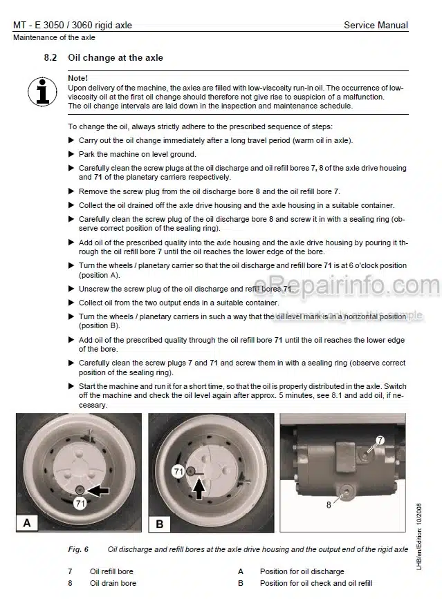
Rigid Axle ZP With Disk Brake
Differential ZP
Differential Kessler
-STEERING
Hydrostatic Steering
Servostat
Steering Cylinder
Flow Indicator
Four Wheel Steering
-OSCILLATING AXLE STABILIZER
Oscillating Axle Stabilizer
Oscillating Axle Stabilizer with Automatic
Stabilizing Cylinder
-BRAKE SYSTEM
General Data and Operating Pressures
Hydraulic Brake System
Compact Brake Block
-SPECIAL ATTACHMENTS/ ADDITIONAL HYDR. INSTALL.
Overload Warning Device
Overload Warning Device – Adjustable
Load Check Valve – Rexroth
Load Check Valve – Oil Control
Load Holding Valve – Oil Control -Independent Of Load And Outgoing Flow Pressure
Hoist Limit
Hydr. Installation Kit
Central Lubrication System
Installation Kit – Travel – Outriggers
Straight Blade
4 – Point Blade And Outrigger Support
Individual Outrigger Control
Outrigger Control
Elevated Cab – Adjustable
Elevated Cab – Hydraulically Adjustable
Elevated Cab With Lifting Stage
Quick Change Coupler
Quick Change Adapter
Industrial Shut Off
Change Over High Pressure Limiting
Hydraulic Hammer – General Data
Install. Kit Change Over Hammer / Rammer
-CAB / HEATER AIR CONDITIONING SYSTEM
Heater D 1 LC
Heater D 3 L C
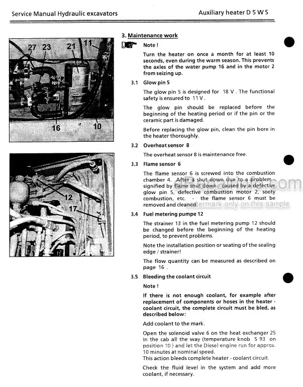
Supplementary Heater D5W
Air Conditioning System Konvekta
-UNDER – / UPPERCARRIAGE ATTACHMENTS
Combinations
Expander Bolt
Tooth System
Shut Off Installation For Grapple Operation
-ARRANGEMENT OF TANKS
Tank Configuration
What you get
You will receive PDF file with high-quality manual on your email immediately after the payment.
Reviews
There are no reviews yet.