Factory Service Manual For Liebherr Wheel Loader. Manual Contains Illustrations, Instructions, Diagrams For Step By Step Remove And Install, Assembly And Disassembly, Service, Inspection, Repair, Troubleshooting, Tune-Ups.
Format: PDF
Language: English
Pages: 477
Issued: 1989-1991
Wiring Diagrams: Yes
Hydraulic Diagrams: Yes
Model
Liebherr Wheel Loader
L551
Serial number-from 0101
Contents
-SAFETY INFORMATION
-GENERAL
Conversion Chart
Tightening Torques
ISO
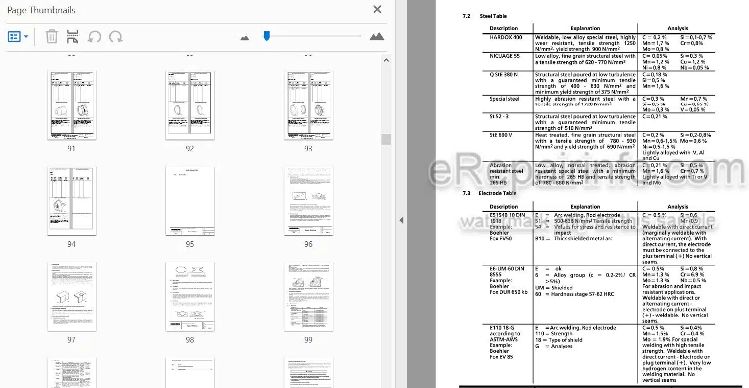
Material Classification
-SPECIAL TOOLS
Gauge Coupling
Deviation Indicator
Piston Wrench
-REPAIR WELDING
-LUBRICANTS
General
Lubrication And Operating Fluids
Lubrication Chart
-TECHNICAL DATA AND INSPECTION SCHEDULES
Adjustment Checklist
Technical Data
Inspection Schedule
Traction diagram
Maintenance and Inspections
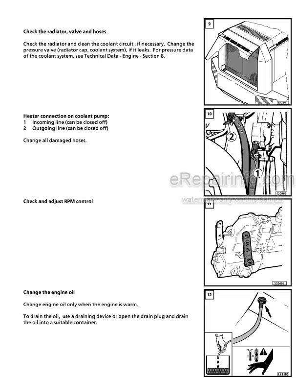
-DIESEL ENGINE/CLUTCH
Liebherr Engine D 906 TI / D 916 TI
Solenoid / Engine Shut Off
Clutch
-PUMP DISTRIBUTOR GEAR
Description And Drawing Of The Gear Box
-TRAVEL HYDRAULIC SYSTEM
Operating Pressures- Travel Hydraulic
Travel Hydraulic System
Variable Hydraulic Pump A 4 V DA Performance Diagram – Travel Hydraulic
Variable Hydraulic Motor A 6 VM DA Regulator Valve
Replenishing Pressure Relief Valve
Crossover Relief Valve
Pressure Cutoff Valve
Inching Valve
-WORKING HYDRAULIC SYSTEM
Operating Pressures
Working Hydraulic System
Variable Displacement Rump
Pump Performance Diagram
Control Valve – General Information – Leak Oil Data
Control Valve NG 22
Relief Valve
Thermostat Valve
Pilot (Servo) Control
Pilot Control Valve
Hydraulic Cylinder
-ELECTRICAL SYSTEM
Electrical System
Battery
Starter
Alternator
Pre-Heating System – Glow Plug
Electrical System
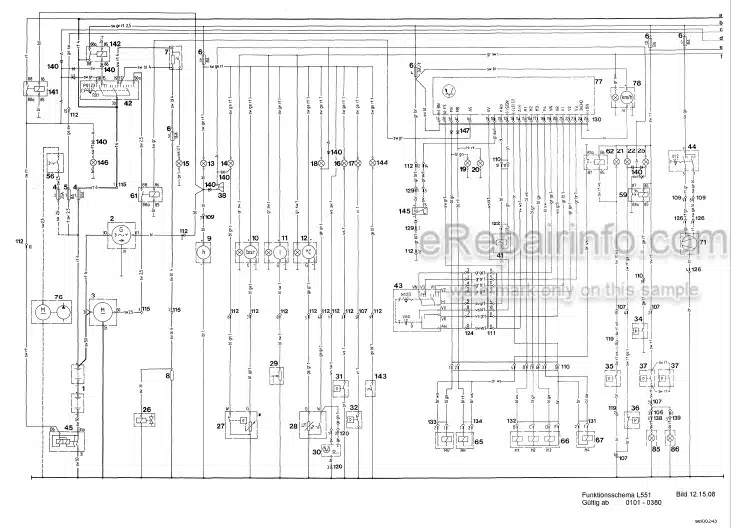
Functional Diagram
Electrical System; Functional Diagram
Instrument/Tachometer / Diode Board
Proximity Switch
-HEATING AND VENTILATION SYSTEM
Heating And Ventilation System
-POWERSHIFT TRANSMISSION
Powershift Transmission 3 AVG 310
Troubleshooting
Powershift Transmission
Bypass – Valve
Shifting Unit 3AVG310
-AXLES
General
Differential
Wheel Hub
-STEERING
General Data
Hydraulic Steering System
Valve Block
Servostat
Servostat Valve
Steering Cylinder
-BRAKE SYSTEM
General Information
Hydraulic Brake System
Cut Off Valve
Service Brake Valve
Parking Brake Valve
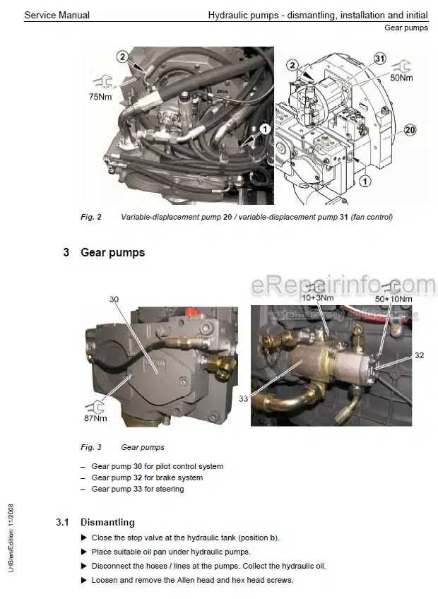
Gear Pump
Accumulator
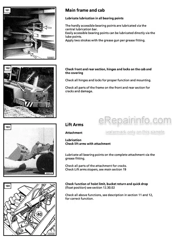
-MAIN FRAME/CAB
Description of Removal / Installation of Articulation and Oscillating Axle
Description and Construction of Cab
-LIFT ARMS
Lift Arms
What you get
You will receive PDF file with high-quality manual on your email immediately after the payment.
Reviews
There are no reviews yet.