


Factory Service Manual For Liebherr Hydraulic Excavator. Manual Contains Illustrations, Instructions, Diagrams For Step By Step Remove And Install, Assembly And Disassembly, Service, Inspection, Repair, Troubleshooting, Tune-Ups.
Format: PDF
Language: English
Pages: 818
Issued: december 2008
Bookmarks: Yes
Searchable: Yes
Wiring Diagrams: Yes
Hydraulic Diagrams: Yes
Model
Liebherr Hydraulic Excavator
R914C-from serial number 19527
R924C-from serial number 19846
Contents
-GENERAL INFORMATION
Safety Instructions
Tightening Torques (Liebherr Standard WN 4037)
Assembly Instruction For Pistons And Piston Nuts (Hydraulic Cylinders)
Assembly Instruction For Piston Rod Bearings With External Threads (Hydraulic Cylinders)
Tightening Torques Of Screws With LH-Washer 340HV
Preloads And Tightening Torques (Din 13)
-TOOLS
Special Tools For Maintenance And Repair
Special Tools For Liebherr Diesel Engine
Special Tools For The Hydraulic System
Special Tools For Electrical Connectors
Special Tools For Gears
Common Tools
Measuring Tool For Spool Travel
Tools For Hydraulic Piston
Slotted Nut Wrench For The Slotted Nut On The Swing Gear SAT
Mounting Device For Disk Brake On Swing Gear SAT
Mounting Device For Disk Brake On Travel Gear
Mounting Device For Disk Brake On Travel Gear
Eichwerten Lms System / Valeurs De Calibrage
Mounting Tool For Sleeping Seal
-TECHNICAL DATA / MAINTENANCE GUIDELINES
Technical Data
Inspection And Maintenance Schedule
Lubrication Chart
-ENGINE
Technical Data for LIEBHERR Engine Type: D 934 S A6
-COUPLING/SPLITTERBOX
Coupling
Splitterbox
-HYDRAULIC SYSTEM
Adjustment Check List
Hydraulic Diagram
-HYDRAULIC COMPONENTS
Installation And Dismantling / Start-Up Of Hydraulic Pumps
Double Variable-Displacement Pump DPVP 108
HMF 75-02P Hydraulic Fixed-Displacement Motor
Hydraulic Cylinders
Extension And Retraction Speeds
Tightening Values For Pistons And Piston Nuts
Hydraulic Cylinder – R 914 C / R 924 C
2-Way Servo Control
4-Way Servo Control
Control Valve Complete For: R924 Compact
Control Plate
Inspecting The Control Valve Blocks For Leak Oil
1-Way Rotary Connection
5-Way Rotary Connection
7-Way Rotary Connection
-ELECTRICAL SYSTEM
Arrangement Of Components
Electrical Diagram
-BALL SLEWING RING
Ball Slewing Ring
-TRAVEL GEAR TRANSMISSION / AXLE TRANSFER CASE
Travel Gear Brake
Slide Ring Seal
-TRAVEL GEAR AXLES
Wear Of Travel Gear Parts
Wear Limits B60/B60L And D6C
Wear Limits D7 & B6HD – B6
Dismantling And Installing Travel Gear Parts
Installing And Dismantling Idler «Berco»
Tensioning Unit
Track Roller
Carrier Roller
-SPECIAL EQUIPMENT MOUNTING KITS
Hydraulic Installation Kit
Schematics Chart For The Options
Hydraulic Schematics For Options
Electric Schematics For Options
-CAB / HEATER / AIR CONDITIONING SYSTEM
Auxiliary Heating
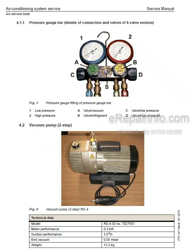
Heating And Air-Conditioning System
-CENTRAL LUBRICATION
Lube Hoses Repair Instructions
Centralized Lubrication System
Pump Of The Centralized Lubrication System
Progressive Distributor SX-E
Progressive Distributor MX-F
What you get
You will receive PDF file with high-quality manual on your email immediately after the payment.


Reviews
There are no reviews yet.