


Factory Service Manual For Liebherr Pipe Layer. Manual Contains Illustrations, Instructions, Diagrams For Step By Step Remove And Install, Assembly And Disassembly, Service, Inspection, Repair, Troubleshooting, Tune-Ups.
Format: PDF
Language: English
Pages: 855
Number: 12228822 (January 2020)
Wiring Diagrams: Yes
Hydraulic Diagrams: Yes
Model
Liebherr Pipe Layer
RL66-1633-15104 G6.0 1504
Contents
-INTRODUCTION
Safety Instructions
Special Tools For Maintenance And Repair Work
Standards And Specifications
Conservation Guidelines
Repair Welding
Hydraulic Symbols
Electrical Symbols
Material Weights
-TECHNICAL DATA
Overall Machine
Drive Group
Cooling System
Working Hydraulics
Travel Hydraulics
Hydraulic Components
Electrical System
Travel Gearbox
Travel Gear, Axles, Tyres, Drive Shafts
Steel Components Basic Machine
Working Attachment
-MAINTENANCE
Maintenance And Inspection Schedule
Fill Quantities, Lubrication Schedule
Lubricants And Fuels
Maintenance Tasks
Overall Machine
Drive Group
Cooling System
Travel Hydraulics
Hydraulic Components
Electrical System
Travel Gearbox
Travel Gear, Axles, Tyres, Drive Shafts
Steel Components Basic Machine
Working Attachment
Operator’s Cab, Heating, Air Conditioning
Testing And Adjustment Checklist
Check And Adjustment Tasks
-DRIVE GROUP
Diesel Engine
Clutch
Splitterbox
Couplings – Pump Output
-Cooling System
Complete Cooling System
Cooler Arrangement
Hydraulic
-WORKING HYDRAULICS
Full Overview-Working Hydraulic
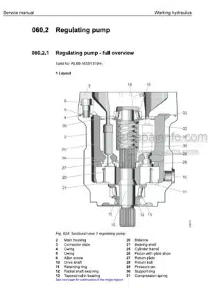
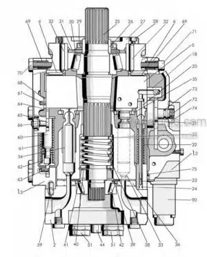
Regulating Pump
Proportional Control Valve Block
Pilot Control
Working Hydraulic
Variable Displacement Motor
Hoist Gear
-TRAVEL HYDRAULICS
Travel Hydraulics Overview
Double Gear Pump – Replenishing
Variable Displacement Pump
Variable Displacement Motors
Distributor Block
-HYDRAULIC COMPONENTS
Hydraulic Cylinder
Valves
Hydraulic Tank
-BRAKE SYSTEM
Inching Brake Pedal
-ELECTRICAL SYSTEM
Electrical System-Full Overview
Lighting System
Circuit Diagrams
Electrical Components Of Operator’S Cab
Electrical Components-Diesel Engine
Electrical Components – Main Frame
Electrical Components Compartments
Display Unit
Electrical Components Litu2 (Option)
Electrical Components Litu3 (Option)
Ego Load Torque Limitation Display Unit
Putting Ego Load Torque Limitation Into Service
Electrical Components Of Ego Load Torque Limitation
Putting Lh Load Torque Limitation Into Service
Electrical Components Of Lh Load Torque Limitation
-TRAVEL GEARBOX
Travel Gearbox, Overall
Brake System
Duo Cone Slipring Seal
External Oil Supply
-TRAVEL GEAR, AXLES, TYRES, DRIVE SHAFTS
Travel Gear Frame
Idler
Tension Unit – Removal
Tension Unit-Installation
Track Roller
Carrier Roller
Function, Wear And Evaluation
-STEEL COMPONENTS BASIC MACHINE
Equalizer Bar
Hoist Gear
-WORKING ATTACHMENT
Rope Winch
Installation Kit, Pipe Chamfering Device And Welding Generator
-OPERATOR’S CAB, HEATING, AIR CONDITIONING
Operator’S Platform
Operator’S Cab
Heater And Ventilation
-SERVICE CODES, DIAGNOSTICS
Testing And Adjustment Software
What you get
You will receive PDF file with high-quality manual on your email immediately after the payment.


Reviews
There are no reviews yet.