


Factory Service Manual For Link-Belt Excavator. Manual Contains Illustrations, Instructions, Diagrams For Step By Step Remove And Install, Assembly And Disassembly, Service, Inspection, Repair, Troubleshooting, Tune-Ups.
Format: PDF
Language: English
Pages: 286
Bookmarks: Yes
Searchable: Yes
Wiring Diagrams: Yes
Hydraulic Diagrams: Yes
Model
Link-Belt Excavator
253X3
Contents
-LOWER
Specifications
Main Equipment Table
Main Equipment Structure and Operation Explanation
Port Diagram
Basic Functions
Removal and Installation of Track
Removal and Installation of Shoe Assembly
Removal and Installation of Shoe Plate
Removal and Installation of Roller
Removal and Installation of Upper Roller
Assembly and Disassembly of Upper Roller
Removal and Installation of Lower Roller
Assembly and Disassembly of Lower Roller
Removal and Installation of the Sprocket
Removal and Installation of Take-up Roller
Assembly and Disassembly of Take-up Roller
Removal and Installation of Grease Cylinder
Assembly and Disassembly of Tension Shock Absorber
Removal and Installation of Center Joint
Assembly and Disassembly of Center Joint
Removal and Installation of Travel Motor
Assembly and Disassembly of Travel Motor
Maintenance Standards
Pressure Measurement and Adjustment Procedures
Drain Volume Measurement Procedures
Air Bleed Procedure
-SWING UNIT, COUNTERWEIGHT
Specifications
Main Equipment Table
Main Equipment Structure and Operation Explanation
Port Diagram
Basic Functions
Removal and Installation of Swing Unit
Assembly and Disassembly of Swing Motor
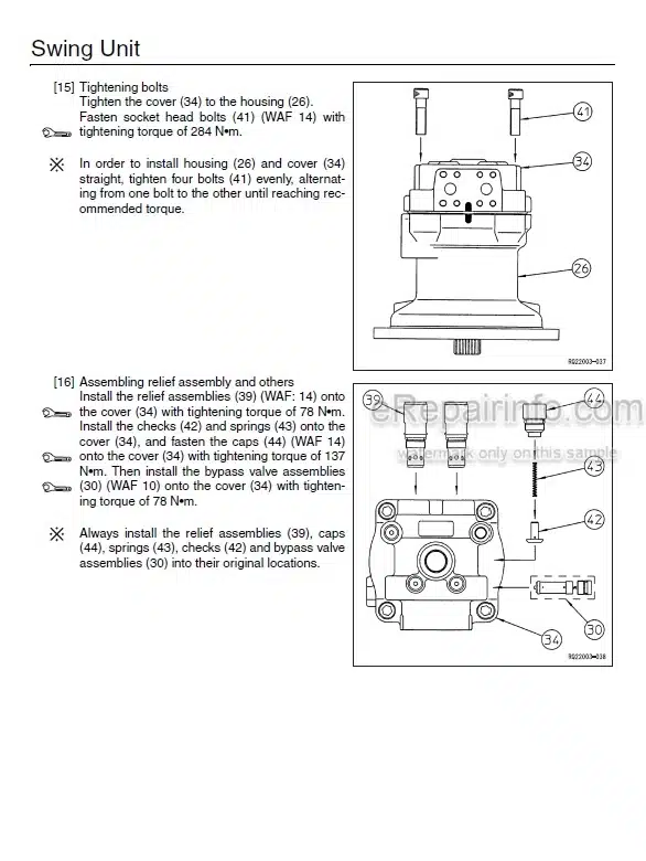
Assembly and Disassembly of Swing Unit
Removal and Installation of Counterweight
Pressure Measurement and Adjustment Procedures
Drain Volume Measurement Procedures
Air Bleed Procedure
-EXPLANATION OF HYDRAULIC CIRCUIT AND OPERATIONS (STANDARD MODEL)
Travel Circuit
Swing Circuit
Boom Circuit
Arm Circuit
Bucket Circuit
Negative Control Circuit
Horsepower Boost Circuits
Other Circuits
-EXPLANATION OF HYDRAULIC CIRCUIT AND OPERATIONS (OPTION)
Breaker Circuit (Independent Operation)
Double-Acting Circuit (Hydraulic Fork)
Multi-Purpose Circuit (Breaker Q Control)
Multi-Purpose Circuit (2 Pumps Flow Crusher)
2nd Option Circuit (Hydraulic Rotation Fork)
What you get
You will receive PDF file with high-quality manual on your email immediately after the payment.


Reviews
There are no reviews yet.