


Factory Service Manual For Link-Belt Excavator. Manual Contains Illustrations, Instructions, Diagrams For Step By Step Remove And Install, Assembly And Disassembly, Service, Inspection, Repair, Troubleshooting, Tune-Ups.
Format: PDF
Language: English
Pages: 835
Searchable: Yes
Wiring Diagrams: Yes
Hydraulic Diagrams: Yes
Model
Link-Belt Excavator
290X2
Contents
-MAIN BODY
Specifications
-SUMMARY
Main Equipment Table
Equipment Layout Diagram
Standard Machine Option List
-HYDRAULICS
Hydraulic Equipment Layout
Port Diagram
Pilot Hose Connection Diagram
Function List
Explanation of Hydraulic Circuit and Operations (Standard Model)
Explanation of Hydraulic Circuit and Operations (Option)
Main Equipment Structure and Operation Explanation
-ELECTRICS
Explanation of New Functions
Electrical Equipment Layout Diagram
Main Equipment Structural Diagrams
Electrical Circuit Diagram
Electrical Connector Wiring Diagram
Electrical Parts and Wiring Assembly Diagram
Explanation of Functions and Operations
Service Support
-ENGINE
Engine Summary
Explanation of Engine Terms
Explanation of Engine Structure
Explanation of Engine Operation
Engine Maintenance Standards
Engine Equipment Table
Exhaust Gas Regulations
Cautions for Fuel Used
-AIR CONDITIONER
Changes from LX
Layout Diagram
Circuit Diagram
Explanation of Functions
Actuator Inspection
Self-diagnosis Function With Panel Display
Part Function and OK / NG Judgment
-NEW MACHINE PERFORMANCE
New Machine Performance
-MAINTENANCE
Pressure Measurement and Adjustment Procedures
Hydraulic Pump Flow Measurement Procedure
Drain Volume Measurement Procedure
Air Bleed Procedure
Procedures for Replacing Consumable Parts
Periodic Maintenance Procedures
Bolt Size and Torque Table
-DATA
Main Unit Weight
Interchangeability
Attachment Installation Methods
Paint Colors
Unit Conversion Ratio
-MAINTENANCE
Electric Equipment Checking Procedure
-ASSEMBLY AND DISASSEMBLY
Lower Mechanism: Track Shoe
Lower Mechanism: Travel Drive Unit
Upper Swing Body: Remote Control Valve
Upper Swing Body: Control Valve
Upper Swing Body: Solenoid Valve
Upper Swing Body: Tank
Light
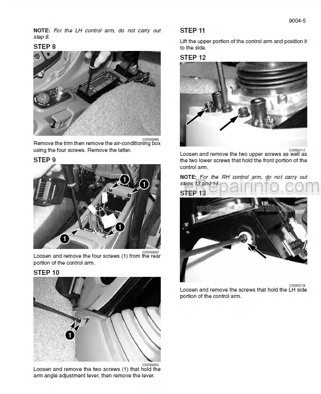
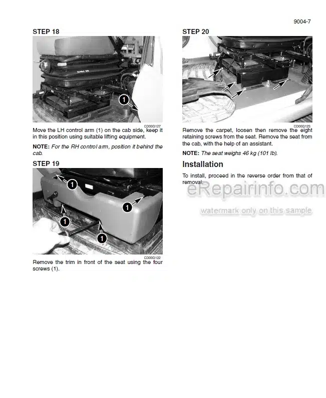
Procedures for Removal and Installation of Cab Inner and Outer Parts
Hydraulic Equipment
290 X2 EX SERVICE MANUAL
290 X2 EX ELECTRICAL SCHEMATIC (PRINT A)
290 X2 EX ELECTRICAL SCHEMATIC (PRINT B)
290 X2 EX ELECTRICAL SCHEMATIC DIAGRAM KBR10920-E14 A
290 X2 EX ELECTRICAL SCHEMATIC DIAGRAM KBR10920-E14
290 X2 EX HYDRAULIC SCHEMATIC
What you get
You will receive PDF file with high-quality manual on your email immediately after the payment.


Reviews
There are no reviews yet.