


Factory Service Manual For Link-Belt Excavator. Manual Contains Illustrations, Instructions, Diagrams For Step By Step Remove And Install, Assembly And Disassembly, Service, Inspection, Repair, Troubleshooting, Tune-Ups.
Format: PDF
Language: English
Pages: 1309
Issued: september 2011
Bookmarks: Yes
Searchable: Yes
Wiring Diagrams: Yes
Hydraulic Diagrams: Yes
Model
Link-Belt Excavator
350X3
Contents
-SAFETY
Safety, General Information And Standard Torque Data
General Information
Standard Torque Data For Cap Screws And Nuts
-LOWER
Specifications
Main Equipment Table
Main Equipment Structure and Operation Explanation
Port Diagram
Basic Functions
Removal and Installation of Track
Removal and Installation of Shoe Assembly
Removal and Installation of Shoe Plate
Removal and Installation of Roller
Removal and Installation of Upper Roller
Assembly and Disassembly of Upper Roller
Removal and Installation of Lower Roller
Assembly and Disassembly of Lower Roller
Removal and Installation of Sprocket
Removal and Installation of Take-up Roller
Assembly and Disassembly of Take-up Roller
Removal and Installation of Grease Cylinder
Assembly and Disassembly of Grease Cylinder
Removal and Installation of Center Joint
Assembly and Disassembly of Center Joint
Removal and Installation of Travel Motor
Assembly and Disassembly of Travel Motor
Maintenance Standards
Pressure Measurement and Adjustment Procedures
Drain Volume Measurement Procedures
Air Bleed Procedure
-SWING UNIT, COUNTERWEIGHT
Specifications
Main Equipment Table
Main Equipment Structure and Operation Explanation
Port Diagram
Basic Functions
Removal and Installation of Swing Unit
Assembly and Disassembly of Swing Motor
Assembly and Disassembly of Swing Unit
Removal and Installation of Counterweight
Pressure Measurement and Adjustment Procedures
Drain Volume Measurement Procedures
Air Bleed Procedure
-ENGINE
Specifications
Main Equipment Table
Basic Functions
Primary Specifications
Function, Structure, Operation
Symptom
Functional Inspection
Maintenance Precautions
Removal And Installation Of Engine Assembly
Removal And Installation Of The Fuel Cooler Engine Inter-Cooler Radiator And Oil Cooler
Removal And Installation Of Turbo Charger
Removal And Installation Of EGR Cooler And EGR Valve
Removal And Installation Of Engine Hood
Removal And Installation Of Muffler
Removal And Installation Of Cylinder Head Cover
Removal And Installation Of Cylinder Block
Lubrication System
Cooling System
Removal And Installation Of Exhaust Manifold
Disassembly, Removal And Installation Of DPD Assembly
Removal And Installation Of Fuel Tank
Removal And Installation Of Fuel Supply Pump
Removal And Installation Of Common Rail Assembly
Removal And Installation Of Injector
Removal And Installation Of Starter Motor
Removal And Installation Of Alternator
Preheating System
Introduction To The Trouble Diagnosis
-HYDRAULIC EQUIPMENT (PUMP, OPERATION SYSTEM VALVE)
Specifications
Main Equipment Table
Basic Functions
Port Diagram
Main Equipment Structure and Operation Explanation
Control Valve
4 Stack Solenoid Valve Operation Explanation
Upper Pilot Valve (remote control valve)
Travel Pilot Valve (remote control valve)
Cushion Valve
Removal and Installation of Hydraulic Oil Tank
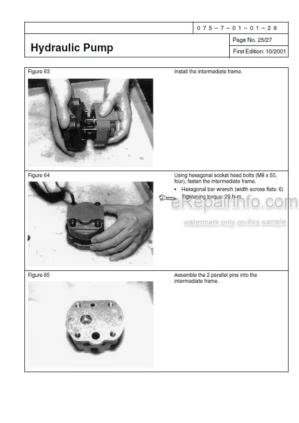
Removal and Installation of Hydraulic Pump
Removal and Installation of Control Valve
Removal and Installation of Pilot Blocs
Removal and Installation of Travel Remote Control Valve
Removal and Installation of Operation Remote Control Valve
Removal and Installation of 4 Stack Solenoid
Removal and Installation of Cushion Valve
Procedures for Assembly and Disassembly of Hydraulic Pump Main Unit
Pump Main Unit Maintenance Standards
Procedures for Assembly and Disassembly of Control Valve
Procedures for Assembly and Disassembly of Operation Remote Control Valve
Procedures for Assembly and Disassembly of Travel Remote Control Valve
Assembly and Disassembly of Cushion Valve
Pressure Measurement and Adjustment Procedures
Hydraulic Pump Flow Measurement Procedures
Air Bleed Procedure
Hydraulic Equipment Layout
Overall View
-CAB
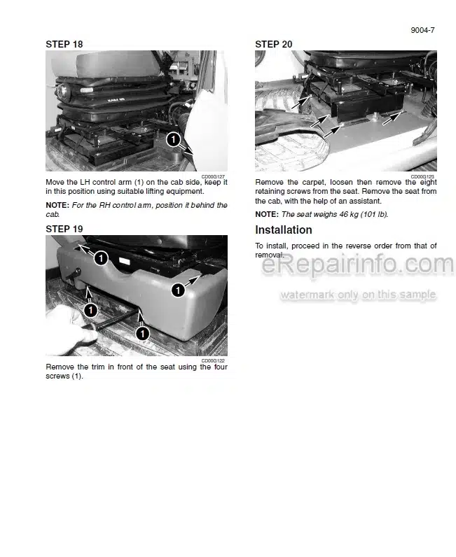
Removal and Installation of Operator’s Seat
Removal and Installation of Cab Assembly
Removal and Installation of Wiper
Removal and Installation of Cab Front Glass
Window Lock Adjustment Procedures
Tightening Torque
-ELECTRICAL PARTS
Electrical And Engine Functions And Service Support
Basic Functions
Accessories
Milli-Amp List
Safety
Service Support
Setting
Explanation On The Computers
Connection Connector Pin Layout
Sequence Circuit Diagram
Block diagram
Electrical Equipment Layout Diagram
Removal and Installation of Wiper Controller
Removal and Installation of Wiper Motor
Removal and Installation of Monitor
Air Conditioner Overall Diagram
Assembly and Disassembly of Unit
Removal and Installation of Compressor
Removal and Installation of Condenser
Removal and Installation of Receiver Dryer
Work Precautions
-ATTACHMENTS
Main Equipment Table
Maintenance Standards
Removal and Installation of Bucket Cylinder
Removal and Installation of Arm Cylinder
Removal and Installation of Boom Cylinder
Procedures for Operation/Assembly and Disassembly of Hydraulic Cylinder
Removal and Installation of Bucket
Removal and Installation of Bucket Link
Removal and Installation of Arm
Removal and Installation of Boom
-OTHER
Specifications
Main Unit Weight
Bolt Size And Torque Table
Overall View
Work Range Diagram
New Machine Performance Judgment Table
Fluids And Lubricants
Main Unit-Side Dtc List
Main Unit-Side Trouble
List Of Special Tools
350X3 ELECTRICAL SCHEMATIC I
350X3 ELECTRICAL SCHEMATIC II
350X3 HYDRAULIC SCHEMATIC
What you get
You will receive PDF file with high-quality manual on your email immediately after the payment.


Anonymous (verified owner) –
Excellent!