


Factory Service Manual For Link-Belt Excavator. Manual Contains Illustrations, Instructions, Diagrams For Step By Step Remove And Install, Assembly And Disassembly, Service, Inspection, Repair, Troubleshooting, Tune-Ups.
Format: PDF
Language: English
Pages: 781
Issued: 2005-2006
Searchable: Yes
Wiring Diagrams: Yes
Hydraulic Diagrams: Yes
Model
Link-Belt Excavator
800LX
Tier III
Contents
-MAIN BODY
Specifications
Emission Control Regulation of 3rd-Stage
Major Equipment Specifications
-HYDRAULIC
Hydraulic Pump
Control Valve
Swing Unit
Travel Unit
Fan Motor for Hydraulic Drive
-HYDRAULIC CIRCUITS
Port Locations
Pilot Hose Connection Diagrams
Functional Explanation
Travel Circuits
Swing Circuits
Arm Circuits
Boom Circuits
Backup Circuits
Other Circuits
Circuit Diagrams
-ELECTRIC CIRCUITS
Operation Explanation
Service Support
Measuring Electrical Device
Initial Controller Settings
Troubleshooting
Electric Wiring Diagrams
Harness Diagrams
Circuit Diagrams
-MAINTENANCE
New Machine Performance
Instructions For Measuring And Adjusting Pressure
Maintenance Of The Circumference Of Engine
Main Body Weight
Attachments Dimensions
Compatibility
Plastic Shim
Procedures For Changing Operation Type
-ASSEMBLY AND DISASSEMBLY
Summary of Assembling
Summary of Disassembling
Attached Data
Appendix
-ABOUT THIS SHOP MANUAL
Safety
Introduction
Using Technical Information
Precautions for Use
Tightening Torque
Numerical Conversion Table
-SPECIFICATIONS
Major Equipment Specifications
Fuel / Lubricants and Filters
-PERFORMANCES
Lifting Capacity
Hydraulic Pump Control Curve
-DISASSEMBLING AND MAINTENANCE INSTRUCTIONS FOR MAIN BODY
Maintenance Instructions
Lower Mechanism
Upper Mechanism
Attachments
-DISASSEMBLING AND MAINTENANCE INSTRUCTIONS FOR MAJOR PARTS
Take-up Roller
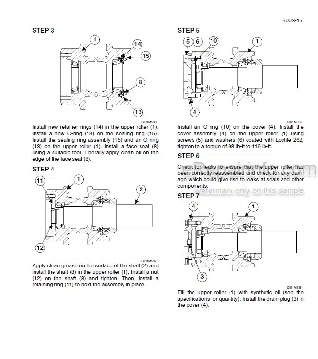
Upper Roller
Lower Roller
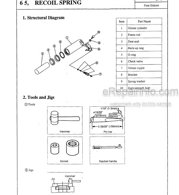
Grease Cylinder
Rotating Joint
Air Conditioner
Maintenance Standards
-DISASSEMBLING AND MAINTENANCE INSTRUCTIONS FOR MAJOR HYDRAULIC COMPONENTS
Hydraulic Pump
Travel Unit
Swing Unit
Control Valve
Cylinder
Remote Control Valve
Solenoid Valve (8-way)
Cushion Valve
Fan Motor
Fan Pump
-INSTRUCTIONS FOR REPAIR
Attachment Reinforcement Procedures
Platform Plate for Repair
What you get
You will receive PDF file with high-quality manual on your email immediately after the payment.


Reviews
There are no reviews yet.