


Factory Service Manual For Link-Belt Wheel Loader. Manual Contains Illustrations, Instructions, Diagrams For Step By Step Remove And Install, Assembly And Disassembly, Service, Inspection, Repair, Troubleshooting, Tune-Ups.
Format: PDF
Language: English
Pages: 723
Issued: november 2004
Bookmarks: Yes
Searchable: Yes
Wiring Diagrams: Yes
Hydraulic Diagrams: Yes
Model
Link-Belt Wheel Loader
L130
Contents
-DESCRIPTION AND DIMENSIONS
Specifications
Standard Equipment
-STANDARD TORQUE SPECIFICATIONS
Torque Specifications – Decimal Hardware
Torque Specifications – Metric Hardware
Grade 129 Bolts, Nuts, And Studs
Torque Specifications – Steel Hydraulic Fittings
Torque Specifications – O-Ring Face Seal Fitting
-LUBRICATION FLUIDS AND LUBRICANTS
Capacities And Lubricants
Maintenance Schedule
-AIR CONDITIONING SYSTEM
Description
System Checks
Component Identification
Condenser Compressor
Troubleshooting
-ROPS CAB
Description
Removal
Installation
-SEAT AND SEAT BELT
Removal
Installation
-PEDALS, LEVERS AND CABLES
Description
Removal
Installation
-CAB GLASS INSTALLATION
Cab Glass Installation
-WINDSHIELD WIPERS
Front Wiper
Rear Wiper
-ENGINE DESCRIPTION
Engine Description
Engine Maintenance And Repair
-ENGINE, RADIATOR, AND HOOD REMOVAL AND INSTALLATION
Specifications
Hood Removal
Hood Installation
Radiator Removal
Radiator Installation
Engine Removal
Engine Installation
-FUEL SYSTEM DESCRIPTION
Specifications
First And Second Stage Filters
Primary Filter
-STARTER MOTOR REMOVAL AND INSTALLATION
Removal
Installation
-ALTERNATOR REMOVAL AND INSTALLATION
Removal
Installation
-ELECTRICAL SCHEMATICS AND TROUBLESHOOTING
Specifications
Schematic Symbols, Abbreviations, And Definitions
Solenoids
Relays
Angle Sensor
Schematic Color Symbols
Reading Electrical Schematics
Fuse Identification
Relay Identification
Power Supply – Starting Circuit
Engine Stop, Start Locking/Interlock, And Horn
Wiper And Washer
Pressure Switches And Sensors
Emergency Steering
Analogue Sensors
Lighting Equipment
Lighting Equipment Socket
Rotary Beacon, Backup Alarm, Reverse Light, And Radio
Service Brakes
Floating Position Lift Arm
OLS – Ride Control
Proportional Valves
Optional Quick Coupler
Regulating Unit, Operators Seat, Cigarette Lighter, And Optional Plug-In
Air Conditioner
-BATTERY SERVICE
Battery Service Components And Specifications
Special Tools
Safety Notes
Maintenance
Nonspill Caps
Battery Test
Charging A Battery
Preparing A Dry Charged Battery For Use
Using Booster Batteries To Start The Engine
-INSTRUMENT CLUSTER DISPLAY AND CONTROL PANEL
Console Self-Test
DBU Sensor-Self Test
Power Circuit Test
Warning Lights
Screen Display
Keyboard
Multifunction Lever (Switch S23)
Control Panel
Control Levers
-HYDRAULIC STEERING SYSTEM DESCRIPTION
Hydraulic Steering System Components
-STEERING COMPONENTS REMOVAL AND INSTALLATION
Steering Column
Emergency Steering Pump
-STEERING CONTROL VALVE
Description
Removal
Installation
-STEERING CYLINDER
Specifications
Removal
Disassembly
Cleaning And Inspection
Assembly
Installation
-CENTER PIVOT
Description And Parts Breakdown
Disassembly
Inspection
Assembly
-POWER TRAIN
Description, Specifications, Troubleshooting And ZF AEB Starter
Transmission Troubleshooting
ZF AEB Starter
-TRANSMISSION
Description
Removal
Installation
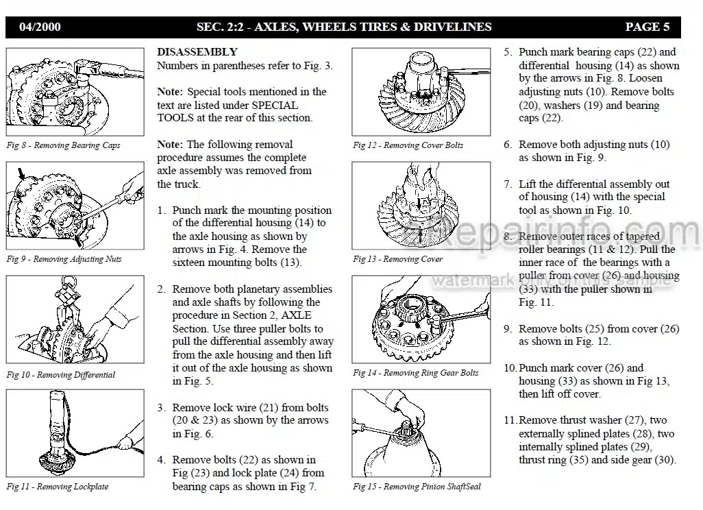
-AXLES
Rear Swing Axle
Front Rigid Axle
-DRIVE SHAFT AND CENTER BEARING
Transmission
Center Drive Shaft
Front Drive Shaft
Rear Drive Shaft
-WHEELS AND TIRES
Wheel Nuts
Tire Pressure
Safety Instructions
Changing Tires
Installing A Wheel
Checking Tire Pressure And Reinflating A Tire
-BRAKE SYSTEM DESCRIPTION
Description
Brake Pump
Brake Valve
Parking Brake
Brake Lines
Service Brakes And Planetary
-BRAKE AND COOLING FAN PUMP
Removal
Disassembly
Inspection
Assembly
Installation
-ACCUMULATORS
Safety
Testing
Adjusting Charging Pressure
Removal
Installation
-BRAKE ACTUATOR VALVE
Removal
Installation
-BRAKE ACCUMULATOR VALVE
Removal
Installation
-PARKING BRAKE
Description
Removal
Installation
-HYDRAULIC SYSTEM DESCRIPTION
Hydraulic Reservoir
Hydraulic Pumps
Brake And Cooling Fan Pump
Main Control Valve
Priority Valve And Steering Valve (Orbitrol)
Cooling Fan Motor
Auxiliary Hydraulic Functions
Ride Control
Pressure Reduction Valve
Oil Cooler
Servo Filter
Hydraulic Test Ports
Brakes
Accumulators
Adjusting Hydraulic Pressure
Troubleshooting
-CLEANING THE HYDRAULIC SYSTEM
General Information
Types Of Contamination
Cleaning The Hydraulic System
Flushing Water From The Hydraulic System
-HYDRAULICS PUMPS
Removal
Installation
-LOADER CONTROL SYSTEM
Description
Removal
Installation
-HYDRAULIC CYLINDERS
Hydraulic Cylinders Location And Parts Breakdown
Removal
Cylinder Parts Breakdown
Disassembly
Inspection
Assembly
Installation
-PRESSURE REDUCTION VALVE
Description And Parts Breakdown
Removal
Installation
Adjustment
-SERVICE TOOL SOFTWARE
Description
ESX Controller
DBU Controller
Angle Sensors
-WHEEL LOADER SOFTWARE INSTALLATION AND DIAGNOSTICS
Wheel Loader Software Installation
Laptop Diagnostics Connection
L130 ELECTRIC SCHEMATIC
L130 ELECTRICAL SCHEMATIC
L130 HYDRAULIC SCHEMATIC
What you get
You will receive PDF file with high-quality manual on your email immediately after the payment.


Anonymous (verified owner) –
Worked great. Huge manual so I took it to a printer to have it printed and bound.