


Factory Repair Manual For Manitou Telescopic Handler. Manual Contains Illustrations, Instructions, Diagrams For Step By Step Remove And Install, Assembly And Disassembly, Service, Inspection, Repair, Troubleshooting, Tune-Ups.
Format: PDF
Language: English
Pages: 986
Issue: january 1997
Bookmarks: Yes
Searchable: Yes
Wiring Diagrams: Yes
Hydraulic Diagrams: Yes
Model
Manitou Telescopic Handler
MLT524
MLT527
MLT628
MLT632
MLT728
Mono-Ultra
Turbo
Turbo Power-Shift Mono-Ultra
MT728-2/4
MT928-4
Turbo
Contents
-GENERAL INSTRUCTIONS AND SAFETY NOTICE
Characteristics
-ENGINE
Removing The Engine And Box Assembly
Engine Disassembly
General Information
Specifications
Service Operations
Cylinder Head Assembly
Piston And Connecting Rod Assemblies
Crankshaft Assembly
Timing Case And Drive Assembly
Cylinder Block Assembly
Engine Timing
Aspiration System
Lubrication System
Fuel System
Cooling System
Flywheel And Housing
Electrical Equipment
List Of Special Tools
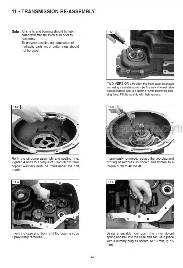
-TRANSMISSION
Gear Box /Converter Disassembly Gear Box “DANA”
Gear Box/Converter Disassembly Gear Box “Power Shift”
-AXLE ASSEMBLY-AXLE
Front Axle Removal
Dismantling Axle
Axle Disassembly
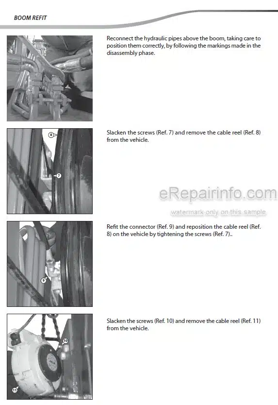
-TELESCOPIC BOOM
Jib Dismantling
Dismantling The Simultaneous Jib
-HYDRAULIC
Rear Steering Cylinder Removal
Cylinder Disassembly
Checking Of Hydraulic Pressures
Hydraulic Diagrams
Hydraulic Circuit
Plate Of Hydraulic Details
Plate Of Attachment Circuit
Operation – Adjustments : Balancing Valve
Test Stand “Valve Adjustment
-ELECTRICITY
Diagram For Fuse And Relay Plate
Electric Diagram
Electric Circuit
Operation Of The “EGS” Shift Lever
Safety System Adjustment
What you get
You will receive PDF file with high-quality manual on your email immediately after the payment.


Reviews
There are no reviews yet.