


Factory Repair Manual For Manitou Telehandler. Manual Contains Illustrations, Instructions, Diagrams For Step By Step Remove And Install, Assembly And Disassembly, Service, Inspection, Repair, Troubleshooting, Tune-Ups.
Format: PDF
Language: English
Pages: 396
Number: 647125EN (september 2015)
Bookmarks
Searchable
Wiring Diagrams
Hydraulic Diagrams
Model
Manitou Telehandler
MLT 634 120 LSU Serie G-E3
MLT 634 120 LSU PS Serie G-E3
MLT 735 100 LSU Serie G-E3
MLT 735 120 LSU Serie G-E3
MLT 735 120 LSU PS Serie G-E3
Contents
-GENERAL CHARACTERISTICS AND SAFETY
General Instructions And Safety Notice
General Control And Adjustment
-ENGINE
Engine Characteristics And Specifications
Engine Components Location
Engine Control And Adjustment
Engine Removal
Engine Refit
-TRANSMISSION
Transmission Schema Tic Diagrams
Transmission Components Location
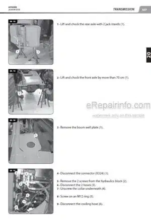
Transmission Control And Adjustment
Transmission Troubleshooting
Specific Transmission Tooling
-AXLE
Axle Control And Adjustment
-BRAKE
Brake Characteristics And Specifications
Brake Components Location
Brake Control And Adjustment
Specific Brake Tooling
-HYDRAULIC
Hydraulic Characteristics And Specifications
Hydraulic Schematic Diagrams
Hydraulic Components Location
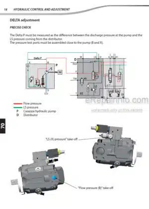
Hydraulic Control And Adjustment
Hydraulic Components Removal
Hydraulic Components Refit
Hydraulic Specific Tooling
-ELECTRICITY
Electrical Characteristics And Specifications
Electrical Schematic Diagrams
Electrical Components Location
Electrical Control And Adjustment
Electrical Components Removal
Electrical Troubleshooting
Electrical Specific Tooling
-DRIVER’S CAB
Driver’s Cab Characteristics And Specifications
Driver’s Cab Components Location
Driver’s Cab Control And Adjustment
Driver’s Cab Troubleshooting
-OPTIONS-ATTACHMENTS
Telehandler Option Configuration
Option Forced Gear
CRC Option: Boom Suspension
ECS (Easy Connecting System) Option
What you get
You will receive PDF file with high-quality manual on your email immediately after the payment.
![Photo 9 - Manitou MT1440 MT1440EP MT1440A MT1840R MT1840 MT1840EP MT1840A Repairs Manual Access Paltform[S]](https://erepairinfo.com/wp-content/uploads/2020/05/Manitou_MT1840_Repairs_Manual_Access_Paltform_2020-04-07_9-37-31-300x415.jpg.webp "Product Manitou MT1440 MT1440EP MT1440A MT1840R MT1840 MT1840EP MT1840A Repairs Manual Access Paltform[S]")


Reviews
There are no reviews yet