


Factory Repair Manual For Manitou Telehandler. Manual Contains Illustrations, Instructions, Diagrams For Step By Step Remove And Install, Assembly And Disassembly, Service, Inspection, Repair, Troubleshooting, Tune-Ups.
Format: PDF
Language: English
Pages: 484
Number: 647681EN (april 2020)
Bookmarks
Searchable
Wiring Diagrams
Hydraulic Diagrams
Model
Manitou Telehandler
MLT 635 130 PS D ST4 S2
MLT 733 105 D ST4
MLT 733 105 D S2
MLT 733 105 D S3
MLT 733 105 D ST4 TRACT
MLT 733 105 D S2 TRACT
MLT 733 105 D S3 TRACT
MLT 733 105 D ST4 TRACT LSU
MLT 733 105 D S2 TRACT LSU
MLT 733 105 D S3 TRACT LSU
MLT 733 115 D ST4
MLT 733 115 D S2
MLT 733 115 D S3
MLT 733 115 D ST4 TRACT
MLT 733 115 D S2 TRACT
MLT 733 115 D S3 TRACT
MLT 733 115 D ST4 TRACT LSU
MLT 733 115 D S2 TRACT LSU
MLT 733 115 D S3 TRACT LSU
MLT 737 130 PS D ST4 S2
MLT 635 140 V PLUS D ST4 S2
MLT 741 140 V PLUS D ST4 S2
MLT 940 140 V PLUS D ST4 S2
MLT-X 737 130 PS D ST3A S1
MLT-X 741 140 V PLUS D ST3A S1
Contents
-GENERAL CHARACTERISTICS AND SAFETY
General Instructions And Safety Notice
General Characteristics And Specifications
General Location
General Control And Adjustment
-ENGINE
Engine Characteristics And Specifications
Engine Schematic Diagrams
Engine Components Location
Engine Controls And Adjustments
Engine Removal – Refitting
Engine Troubleshooting
Specific Engine Tooling
-TRANSMISSION
Transmission Schematic Diagrams
Transmission Locations
Transmission Controls And Adjustments
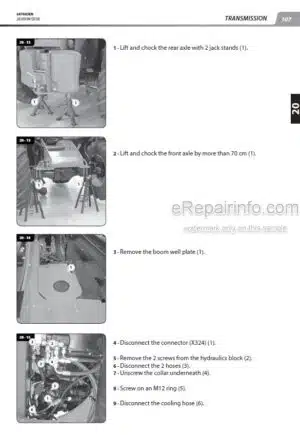
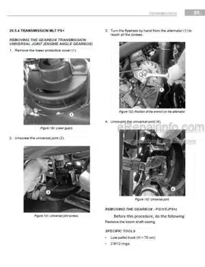
Transmission Removal – Refit
Specific Transmission Tooling
-AXLE
Axle Controls And Adjustments
-BRAKE
Brake Characteristics And Specifications
Service Brake Schematic Diagrams
Brake Locations
Brake Controls And Adjustment
Brake Removal – Refit
Specific Brake Tooling
-BOOM
Boom Characteristics And Specifications
Boom Location
Boom Control And Adjustment
Removal – Refit
Special Boom Tools
-HYDRAULIC
Hydraulic Characteristics And Specifications
Hydraulic Schematic Diagrams
Hydraulic Locations
Hydraulic Controls And Adjustments
Hydraulics Removal – Refit
Hydraulic Specific Tooling
-ELECTRICITY
Electricity Characteristics And Specifications
Wiring Diagrams
Electricity Locations
Electrical Removal – Refit
Electrical Troubleshooting
Specific Electric Tooling
-DRIVER’S CAB
Driver’s Cab Control And Adjustment
Removal – Refitting Driver’s Cab
Specific Cab Tooling
-FRAME-BODY
Removal – Refitting Frame – Bodywork
-OPTIONS – ATTACHMENTS
Intelligent Hydraulics Option
What you get
You will receive PDF file with high-quality manual on your email immediately after the payment.


Reviews
There are no reviews yet