


Factory Repair Manual For Manitou Gear Box. Manual Contains Illustrations, Instructions, Diagrams For Step By Step Remove And Install, Assembly And Disassembly, Service, Inspection, Repair, Troubleshooting, Tune-Ups.
Format: PDF
Language: ENG; GER; ESP; ITA; FRA
Pages: 204
Issue: July 2007 (updated December 2007)
Searchable: Yes
Model
Manitou Gear Box
Series PSR09
Contents
SAFETY PRECAUTIONS
CLEANING AND INSPECTION & LEGEND SYMBOLS
-TECHNICAL SPECIFICATIONS
Identification Of The Unit
Weight, Dimensions, Oil Capacity
Tightening Torques
Clutch Control System
Pressure And Temperature Specifications
Electrical Specifications
Hydraulic Cooler And Filter Line Specifications
-MAINTENANCE
Oil Specification
Sump Preheaters
Normal Oil Change Interval
Extended Oil Change Interval
Filters
Maintenance Intervals
Servicing Machine After Components Overhaul
-INSTALLATION DETAILS
Transmission To Engine Installation Procedure
External Plumbing
Cooler & Filter Lines Specifications
Speed Sensor Installation
-OPERATION OF THE TRANSMISSION
The Transmission Assembly
The Converter, Pump Drive And Pressure Regulating Valve
The Input Shaft And Directional Clutches
The Speed Synchronizer And Output Section
The Output Section
The Transmission Controls
-POWERFLOWS, ACTIVATED SOLENOIDS AND HYDRAULIC CIRCUIT
Powerflows Diagram Neutral Position
Hydraulic Diagrams For Standard Control Valve Neutral Position
Hydraulic Diagrams For Ecmi (Inching Version) Control Valve Neutral Position35
Powerflows Diagram Forward Speed Engaged
Hydraulic Diagrams For Standard Control Valve Forward Position
Hydraulic Diagrams For Ecmi (Inching Version) Control Valve Forward Position
Powerflows Diagram Reverse Speed Engaged
Hydraulic Diagrams For Standard Control Valve Reverse Position
Hydraulic Diagrams For Ecmi (Inching Version) Control Valve Reverse Position
-TROUBLESHOOTING PROCEDURES
Stall Test
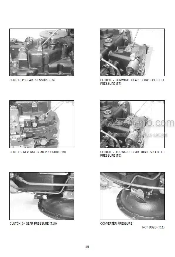
Transmission Pressure Checks
Mechanical And Electrical Checks
Hydraulic Checks
Low Clutch Pressure
Low Charging Pump Output
Overheating
Noisy Converter
Lack Of Power
MAINTENANCE POINTS
-SPEED SENSORS
Removal
Installation
-SAFETY PRESSURE SWITCH
Removal
Installation
-TORQUE CONVERTER AND OIL PUMP
Removal
Installation
-SAFETY VALVE AND PRESSURE REGULATOR VALVE
Removal
Installation
-CONTROL VALVE STANDARD VERSION
Removal
Installation
-CONTROL VALVE INCHING VERSION
Removal
Installation
-GEARBOX CONTROL LEVER
Removal and disassembly
Assembly and installation
-NEGATIVE BRAKE CALLIPER
Removal
Installing and adjusting
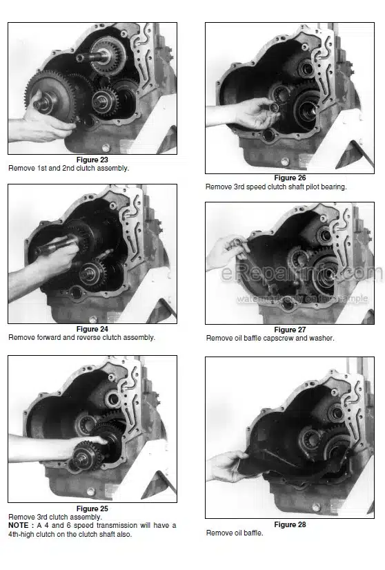
DISASSEMBLING THE CASING AND REMOVING THE GEARBOX
SHAFT ASSEMBLY
INSTALLING THE GEARBOX SHAFT ASSEMBLY AND ASSEMBLING THE CASING
-SECONDARY SHAFT (1st – 2nd GEAR)
Disassembly
Assembly
-PRIMARY SHAFT (3rd – 4th GEAR)
Disassembly
Assembly
CHECKING CONDITION OF GEAR SELECTOR RODS AND YOKES
-BEVEL GEAR PAIR
Removal
Adjusting and Assembling
-PINION
Disassembly
Assembly
-CLUTCH ASSEMBLY
Disassembly
Assembly
SPECIAL TOOLS
What you get
You will receive PDF file with high-quality manual on your email immediately after the payment.

![Photo 10 - Manitou MT1440 MT1440EP MT1440A MT1840R MT1840 MT1840EP MT1840A Repairs Manual Access Paltform[S]](https://erepairinfo.com/wp-content/uploads/2020/05/Manitou_MT1840_Repairs_Manual_Access_Paltform_2020-04-07_9-37-31-300x415.jpg.webp "Product Manitou MT1440 MT1440EP MT1440A MT1840R MT1840 MT1840EP MT1840A Repairs Manual Access Paltform[S]")


Reviews
There are no reviews yet.