


Factory Service Repair Manual For Massey Ferguson 8925 Tractors. Tons of illustrations, instructions, diagrams for step by step remove and install, assembly and disassembly, service, inspection, repair, troubleshooting, tune-ups.
Format: PDF
Language: English
Pages: 670
Bookmarks: Yes
Searchable: Yes
Wiring Diagrams: Yes
Model
Massey Ferguson 8925
Contents
- -FOREWORD
- -SAFETY INSTRUCTIONS
Fire Prevention - -SERIAL NUMBER LOCATIONS
Telescopic Handler Serial Number
Engine Serial Number
Other Serial Numbers - -DELIVERY REPORT
- -TELEHANDLER IDENTIFICATION
- -MAINTENANCE SAFETY
- -SAFETY AND MAINTENANCE
AIR CLEANER SERVICE
Replacing Filter Element
AXLES (FRONT AND REAR)
Checking Oil Level (Front Differential)
Checking Oil Level (Planetary Carrier)
Checking Oil Level (Rear Differential)
Draining Oil (Front Differential)
Draining Oil (Planetary Carrier)
Draining Oil (Rear Differential)
APPROVED BOOM STOP
Installing The Approved Boom Stop
Removing The Approved Boom Stop
ENGINE COOLING SYSTEM
Checking The Coolant Level
Cleaning The Cooling System
Replacing The Coolant
ENGINE COVER
Opening And Closing The Engine Cover
ENGINE LUBRICATION SYSTEM
Checking Engine Oil
Oil Chart
Replacing Oil And Filter
FUEL SYSTEM
Filling The Fuel Tank
Fuel Filter
Fuel Specifications
HYDRAULIC/HYDROSTATIC SYSTEM
Checking And Adding Fluid
Replacing Hydraulic Fluid
Replacing Hydraulic/Hydrostatic Filter
LATERAL OPERATOR RESTRAINT SYSTEM (LORS™)
System Inspection
System Maintenance
LIFTING AND BLOCKING THE VERSAHANDLER
Procedure
LUBRICATION
Procedure
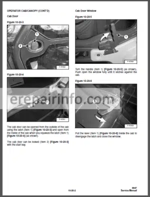
OPERATOR CAB/CANOPY
Cab Door
Cab Door Window
Emergency Exit
SERVICE SCHEDULE
SPARK ARRESTOR MUFFLER
Procedure
TIRE MAINTENANCE
Tire Mounting
Tire Rotation
Wheel Nuts
TOWING THE VERSAHANDLER
Procedure
TRANSPORTING THE VERSAHANDLER
Procedure - -HYDRAULIC SYSTEM
ACCUMULATOR
Not Available At Time Of Printing
BRAKE VALVE
Disassembly And Assembly
Removal And Installation
BUCKET POSITIONING CYLINDER
Assembly
Disassembly
Parts Identification
Removal And Installation
DRIVE BOX
Assembly
Disassembly
Inspection
Parts Identification
EXTENSION CYLINDER
Assembly
Cylinder Group Removal And Installation
Disassembly
Extension Cylinder Removal And Installation
Parts Identification
Tubeline Tray Assembly
Tubeline Tray Disassembly
Upper Tubeline Installation
Upper Tubeline Removal
FAN MOTOR
Not Available At Time Of Printing
FLOW CONTROL VALVE
Removal And Installation
FRONT AUXILIARY HYDRAULIC PRESSURE RELEASE VALVE
Disassembly And Assembly
Removal And Installation
GEAR PUMP
Not Available At Time Of Printing
HYDRAULIC CONTROL VALVE
Not Available At Time Of Printing
Continued On Next Page
HYDRAULIC RESERVOIR
Not Available At Time Of Printing
HYDRAULIC SYSTEM INFORMATION
Tightening Procedures
Troubleshooting Chart
JOYSTICK
Disassembly And Assembly
Handle Removal And Installation
Joystick Removal And Installation
Parts Identification
LIFT CYLINDER
Assembly
Disassembly
Parts Identification
Removal And Installation
MAIN RELIEF VALVE
Removal and Installation
Testing And Adjustment
PARKING BRAKE
Parking Brake Valve Disassembly And Assembly
Parking Brake Valve Removal And Installation
Pressure Switch Disassembly And Assembly
Pressure Switch Removal And Installation
PORT RELIEF VALVES
Adjustment Procedure
PRESSURE REDUCING VALVE
Not Available At Time Of Printing
QUICK TACH CYLINDER
Assembly
Disassembly
Parts Identification
Removal And Installation
STEERING CYLINDER (FRONT)
Assembly
Disassembly
Parts Identification
Removal And Installation
STEERING CYLINDER (REAR)
Assembly
Disassembly
Parts Identification
Removal And Installation
STEERING MODE VALVE BLOCK
Assembly
Disassembly
Parts Identification
Removal And Installation
Solenoid Testing
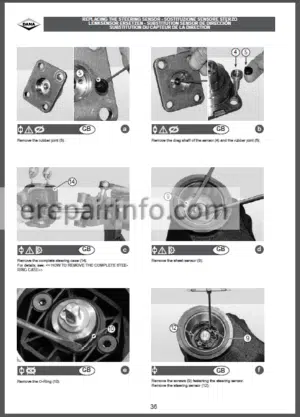
STEERING VALVE
Assembly
Disassembly
Inspection
Parts Identification
Removal And Installation
TILT CYLINDER
Assembly
Disassembly
Parts Identification
Removal And Installation - -HYDROSTATIC SYSTEM
HYDROSTATIC DRIVE MOTOR
Assembly
Disassembly
Inspection
Parts Identification
Removal And Installation
HYDROSTATIC PUMP
Assembly
Disassembly
Inspection
Parts Identification
Removal And Installation
HYDROSTATIC SYSTEM INFORMATION
Replenishing Valve Function
Troubleshooting Chart
OIL COOLER
Not Available At Time Of Printing - -DRIVE SYSTEM
AXLE AND DIFFERENTIAL (FRONT)
Axle Housing/Drive Axle Assembly
Axle Housing/Drive Axle Disassembly
Axle Housing/Drive Axle Parts Identification
Brake Group Disassembly
Brake Group Inspection
Brake Group Parts Identification
Differential Assembly
Differential Disassembly
Differential Inspection
Differential Parts Identification
General Information
Pinion Group Assembly
Pinion Group Disassembly
Pinion Group Inspection
Pinion Group Parts Identification
Planetary Carrier Assembly
Planetary Carrier Disassembly
Planetary Carrier Inspection
Planetary Carrier Parts Identification
Steering Knuckle Assembly
Steering Knuckle Disassembly
Steering Knuckle Parts Identification
Wheel Hub Assembly
Wheel Hub Disassembly
Wheel Hub Inspection
Wheel Hub Parts Identification
AXLE AND DIFFERENTIAL (REAR)
Axle Housing/Drive Axle Assembly
Axle Housing/Drive Axle Disassembly
Axle Housing/Drive Axle Parts Identification
Differential Assembly
Differential Disassembly
Differential Inspection
Differential Parts Identification
General Information
Pinion Group Assembly
Pinion Group Disassembly
Pinion Group Inspection
Pinion Group Parts Identification
Planetary Carrier Assembly
Planetary Carrier Disassembly
Planetary Carrier Inspection
Planetary Carrier Parts Identification
Continued On Next Page
DRIVE SYSTEM
Service Manual
AXLE AND DIFFERENTIAL (REAR)
Steering Knuckle Assembly
Steering Knuckle Disassembly
Steering Knuckle Parts Identification
Wheel Hub Assembly
Wheel Hub Disassembly
Wheel Hub Inspection
Wheel Hub Parts Identification
AXLE TOEIN
Adjustment
DRIVESHAFT
Removal And Installation
FRONT AXLE
Installation
Removal
PARKING BRAKE
ReActivating The Brake
Releasing The Brake For Towing
REAR AXLE
Installation
Removal
SERVICE BRAKE
Bleeding The Brake Circuit
Description
STEERING ANGLE ADJUSTMENT
Adjustment
TROUBLESHOOTING
Chart - -MAIN FRAME
BOOM ASSEMBLY
Removal And Installation
CANOPY
Removal and Installation
DASH COVER/STEERING COLUMN COVER
Removal And Installation
ENGINE COVER
Not Available At Time Of Printing
FENDER
Removal And Installation
FUEL TANK
Not Available At Time Of Printing
INNER BOOM
Installation
Removal
JOYSTICK PANEL
Removal And Installation
OPERATOR CAB
OPERATOR SEAT
Removal And Installation
QUICK TACH
Removal And Installation
REAR WEIGHTS
Not Available At Time Of Printing
WEAR PADS (FRONT)
Removal And Installation
WEAR PADS (REAR)
Installation
Removal - -ELECTRICS & WIRING DIAGRAMS
Introduction
How To Read The Schematic
Wiring Diagrams
Susmic – Table Of Errors
Susmic Testing
Isl Calibration - -ELECTRICAL SYSTEM AND ANALYSIS
ALTERNATOR
Adjusting The Alternator Belt
Removal And Installation
BATTERY
Removal And Installation
Servicing
Using A Booster Battery (Jump Starting)
BRAKE LIGHT SWITCH
Adjustment
Removal And Installation
ELECTRICAL SYSTEM INFORMATION
Description
Fuses, Diodes & Relays
Troubleshooting Chart
FRONT WIPER MOTOR
Removal And Installation
INCHING SWITCH
Adjustment
Removal And Installation
INSTRUMENT PANEL
Removal And Installation
LIGHTS
Front Light Removal And Installation
Rear Light Removal And Installation
PEDAL ASSEMBLY
Disassembly And Assembly
Removal And Installation
REAR WIPER MOTOR
Removal And Installation
SERVICE SOFTWARE
Calibrate Creep Potentiometer
Calibrate Inch Pedal
Connecting The Laptop Computer
Entering The Service Software
Monitor Screen
Program/Update Susmic Controller
Warnings Screen
STARTER
Not Available At Time Of Printing
SWITCH PANEL
Removal And Installation
TOP WIPER MOTOR
Removal And Installation
TRAVEL/SIGNAL LEVER
Removal And Installation - -ENGINE SERVICE
Engine Speed Control
Muffler
Air Cleaner
Radiator
Engine And Engine Mounts
Engine Components And Testing
Eng1Ne/Hydrostat Assembly
Flywheel And Housing
Reconditioning The Engine - -HEATING, VENTILATION, AIR CONDITIONING
AIR CONDITIONING SERVICE
Chart
AIR CONDITIONING SYSTEM FLOW
Chart
Principals
BASIC TROUBLESHOOTING
Checking The Electrical System
Compressor Drive Belt Inspection
Poor A/C Performance
COMPONENTS
Identification
COMPRESSOR
Compressor Clutch Disassembly And Assembly
Removal And Installation
CONDENSER
Removal And Installation
EVAPORATOR/BLOWER UNIT
Removal And Installation
EXPANSION VALVE
Removal And Installation
GENERAL AIR CONDITIONING SERVICE GUIDELINES
Component Replacement And Refrigeration Leaks
Compressor Oil
Compressor Oil Check
HEATER ASSEMBLY
Core Removal And Installation
Fan Removal And Installation
Removal And Installation
PRESSURE SWITCH
Removal And Installation
RECEIVER/DRIER
Removal And Installation
REGULAR MAINTENANCE
Cleaning The Condenser
Compressor Drive Belt Inspection
Filter Element Removal And Installation
SAFETY
Safety Equipment
SYSTEM CHARGING AND RECLAMATION
Charging Procedure
Charging Procedure With A Manifold Gauge Set
Reclamation Procedure
SYSTEM TROUBLESHOOTING CHART
Chart
Gauge Pressure Related Troubleshooting
TEMPERATURE/PRESSURE
Chart - -SPECIFICATIONS
CONVERSIONS
Decimal And Millimeter Equivalents
US To Metric Conversion
ENGINE SPECIFICATIONS
Not Available At Time Of Printing
HYDRAULIC’HYDROSTATIC FLUID SPECIFICATIONS
Specifications
HYDRAULIC CONNECTION SPECIFICATIONS
Flare Atting
O-ring Face Seal Connexion
O-ring Rare Fitting
Port Seal Fitting
Straight Thread O-ring Fitting
TubeGnes And Hoses
MACHINE TORQUE SPECIFICATIONS
Specifications
TORQUE SPECIFICATIONS FOR BOLTS
Torque For General Metric Botts
Torque for General SAE Bolts
VERSAHANDLER SPECIFICATIONS
Capacities
Controls
Dimensional Specifications
Drive System
Electrical System
Engine
Hydraulic System
Instrument Panel
Performance Specifications
Tires
What you get
You will receive PDF file with high-quality manual on your email immediately after the payment.


Reviews
There are no reviews yet.