


Factory Service Repair Manual For McCormick CT28 CT36 Tractors. Tons of illustrations, instructions, diagrams for step by step remove and install, assembly and disassembly, service, inspection, repair, troubleshooting, tune-ups.
Format: PDF
Language: English
Pages: 313
Bookmarks: Yes
Searchable: Yes
Wiring Diagrams: Yes
Hydraulic Diagrams: Yes
Model
McCormick CT28, CT36
Contents
- INTRODUCTION
SERVICE DATA
HOW TO USE THIS MANUAL - -GENERAL INFORMATION
MODEL IDENTIFICATION AND SERIAL NUMBER LOCATION
Model Identification Location
Serial Number Location
COMPONENT LOCATION
S3L/S3L2
S4L/S4L
SPECIFICATIONS
PERFORMANCE CURVES (ONE-HOUR RATING, WITH FAN)
PRIME POWER OUTPUT CHART - -OVERHAUL INSTRUCTIONS
DETERMINING WHEN TO OVERHAUL THE ENGINE
COMPRESSION PRESSURE MEASUREMENT
Inspection
Measurement
TROUBLES HOOTING
General
Engine Troubleshooting
Problem 1: Hard Starting
Problem 2: Fuel Knock
Problem 3: Overheating
Problem 4: Black Exhaust Smoke
Problem 5: Erratic Idle Speeds
Problem 6: Low Power Or Loss Of Power
Starting System Troubleshooting
BASIC PRECAUTIONS FOR DISASSEMBLY AND ASSEMBLY
Disassembly
Assembly - -DISASSEMBLY
PREPARATION FOR DISASSEMBLY
Engine Oil Draining
Coolant Draining
ELECTRICAL SYSTEM
Starter
Alternator
COOLING SYSTEM
Cooling Fan Removal
Thermostat Case Removal
Water Pump Assembly Removal
FUEL SYSTEM
Fuel Injection Pipe Removal
Fuel Injection Nozzle Removal
Governor Assembly Removal
Governor Weight Removal
Fuel Injection Pump Removal
LUBRICATION SYSTEM
Oil Filter Removal
Pressure Relief Valve Removal
Oil Pressure Switch Removal
AIR INLET SYSTEM AND EXHAUST SYSTEM
Exhaust Manifold Removal
Air Inlet Cover Removal
CYLINDER HEAD AND VALVE MECHANISM
Rocker Shaft Assembly Removal
Rocker Shaft Disassembly
Cylinder Head Bolt Removal
Cylinder Head Assembly Removal
Valve And Valve Spring Removal
Valve Stem Seal Removal
TIMING GEARS AND FLYWHEEL
Flywheel Removal
Rear Plate Removal
Oil Seal Case Removal
Tappet Removal
Speedometer Driven Gear Removal
Crankshaft Pulley Removal
Timing Gear Case Removal
Timing Gear Backlash Measurement
Idler Gear Removal
Camshaft Removal
Fuel Injection Pump Camshaft Removal
Gear Removal (When Required)
Oil Pump Removal
Front Plate Removal
CYLINDER BLOCK, CRANKSHAFT, PISTONS AND OIL PAN
Oil Pan Removal
Oil Screen Removal
Thrust Clearance Measurement For Connecting Rod Big End
Connecting Rod Cap Removal
Piston Removal
End Play Measurement For Crankshaft
Main Bearing Cap Removal
Crankshaft Removal
Piston Separation From Connecting Rod - -INSPECTION
CYLINDER HEAD AND VALVE MECHANISM
Cylinder Head
Rocker Arms And Rocker Shaft
Valve Springs
Valve Push Rods
Valves, Valve Guides And Valve Seats
Combustion Jet Replacement
TIMING GEARS AND FLYWHEEL
Camshaft
Fuel Injection Pump Camshaft
Tappets
Idler Gear
Flywheel And Ring Gear
CYLINDER BLOCK, CRANKSHAFT, PISTONS AND OIL PAN
Pistons, Piston Rings And Piston Pins
Connecting Rods
Crankshaft
Cylinder Block - -ASSEMBLY
CYLINDER BLOCK, CRANKSHAFT, PISTONS AND OIL PAN
Main Bearing Installation
Crankshaft Installation
Main Bearing Cap Installation
Side Seal Installation
Piston Assembling To Connecting Rod
Piston Ring Installation
Piston And Connecting Rod Installation
Connecting Rod Cap Installation
Oil Screen Installation
Oil Pan Installation
TIMING GEARS AND FLYWHEEL
Front Plate Installation
Oil Pump Installation
Engine Turning
Fuel Injection Pump Camshaft Installation
Camshaft Installation
Idler Gear Installation
Timing Gear Case Installation
Crankshaft Pulley Nut Tightening
Ptogear Installation
Speedometer Driven Gear Installation
Tappet Installation
Oil Seal Case Installation
Rear Plate Installation
Flywheel Installation
CYLINDER HEAD AND VALVE MECHANISM
Cylinder Head Bottom Face Cleaning
Valve Stem Seal Installation
Valve Spring Installation
Valve Block Installation
Cylinder Head Gasket Installation
Cylinder Head Installation
Cylinder Head Bolt Tightening
Valve Push Rod Installation
Rocker Shaft Assembling
Rocker Shaft Assembly Installation
Valve Clearance Adjustment
Rocker Cover Installation
AIR INLET SYSTEM AND EXHAUST SYSTEM
Air Inlet Cover Installation
Exhaust Manifold Installation
FUEL SYSTEM
Fuel Injection Nozzle Installation
Fuel Injection Pump Installation
Flyweight Assembly Installation
Sliding Sleeve Installation
Governor Assembly Installation
Fuel Injection Line Installation
LUBRICATION SYSTEM
Pressure Relief Valve Installation
Oil Filter Installation
Oil Pressure Switch Installation
COOLING SYSTEM
Water Pump Installation
Thermostat Installation
Cooling Fan Installation
Thermoswitch And Thermounit Combination Installation
ELECTRICAL SYSTEM
Glow Plug Installation
Alternator Installation - -ELECTRICAL SYSTEM
GENERAL
Schematic
Specifications (Standard)
STARTER
Disassembly
Inspection
Assembly
ALTERNATOR
Disassembly
Inspection
Assembly
KEY SHUTOFF SYSTEM (ETS solenoid type)
General
Cord Color (Standard)
Shutoff Solenoid Installation
Inspection After Assembly
KEY SHUTOFF SYSTEM (ETR solenoid type)
General
Cord Color (Standard)
Shutoff Solenoid Installation
AUTOMATIC GLOW PLUG SYSTEM
General
Glow Plug Timer Specifications (Standard)
Glow Plug Relay Specifications (Standard)
Glow Plug Inspection - -COOLING SYSTEM
GENERAL
Schematic
Specifications (Standard)
INSPECTION
Water Pump
Thermostat (Standard )
Thermoswitch (Standard)
Thermo unit (Standard) - -LUBRICATION SYSTEM
GENERAL
Schematic
Specifications
INSPECTION
Oil Pump
Oil Pressure Switch
Pressure Relief Valve - -FUEL SYSTEM
GENERAL
Schematic
Specifications (Standard) ,
Inspection
Disassembly And Assembly
FUEL INJECTION PUMP
Test On Engine
Disassembly
Inspection
Assembly
GOVERNOR
Disassembly And Inspection
Assembly
Torque Spring Set Installation
FUEL PUMP
Inspection
FUEL FILTER - -AIR INLET SYSTEM AND EXHAUST SYSTEM
GENERAL
Schematic
INSPECTION - -MAINTENANCE
LUBRICATION AND MAINTENANCE CHART
ENGINE OIL AND OIL FILTER
Engine Oil Specifications
Oil Level Check
Oil Change
Oil Filter Change
VALVE CLEARANCE
FUEL INJECTION TIMING
Preparation
Inspection
Adjustment
FUEL FILTER
FUEL SYSTEM PRIMING
IDLE RPM SETTING
FUEL INJECTION NOZZLE
Injection Pressure (Valve Opening Pressure) Test
Orifice Restriction Test
Nozzle Tip Washing And Replacement
Installation
FAN BELT - -SERVICE DATA
SPECIFICATIONS
Basic Engine Components
Lubrication System
Fuel System
Air Inlet System And Exhaust System
Cooling System (Standard)
Electrical System
TIGHTENING TORQUES
Major Bolts And Nuts
Torques For Bolts And Nuts With Standard Threads
Torques For Plugs With Taperlock Threads
SEALANTS
SPECIAL TOOLS - -TRANSMISSION
MAIN GEAR (CENTER CASE)
Notice & Index
Schematic View Of Transmission
Specification
Major Specification Of Appearance
Running Speed
Release Bearing Assembly & Fork
Clutch Disassembling & Assembling
Hst Disassembling & Assembling
Hst Operation Principal
Clutch Pedal (Mechanical)
Neutral Adjustment (Hst)
Break Pedal Gap Adjustment
Forward & Backward
Main Gear Changing
Gear Disassembling Of Main Gear Range Gear Change
Pto Drive
Pto Clutch Disassembling & Assembling
Pto Gear Disassembling & Assembling
Composition Principal Of Mid Pto
RANGE GEAR (AXLE CASE)
Power Map Of Range Gear
Range Gear Disassembling & Assembling
Assembling And Disassembling Of Differential Lock
Pinion Shaft Disassembling
Front Wheel Drive Shaft Disassembling & Assembling
FINAL DRIVE SHAFT ( DIFFERENTIAL & REAR DRIVE SHAFT)
General Notices
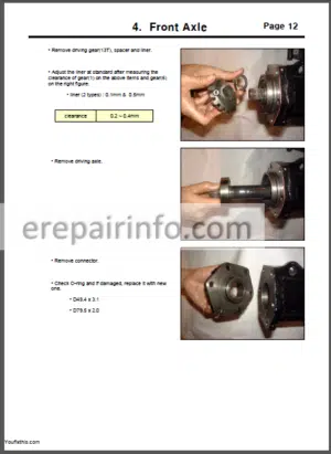
Final Drive Disassembling & Assembling - -FRONT AXLE
- -HYDRAULIC SYSTEM
Main Specification
Construction Of Hydraulic System Of Mechanical Transmission
Schematic Of Hydraulic Circuit Of Mechanical Transmission
Construction Of Hydraulic System Of Hydrostatic Transmission
Schematic Of Hydraulic Circuit Of Hydrostatic Transmission
Hydraulic Pump
Independent Pto
Front Outlet Valve
Control Valve
Neutral Position
Lifting Position
Down Position
Torque For The Bolt Of Hydraulic Housing
Assembly And Disassembly Of Hydraulic Housing
Assembly And Disassembly Of Link
Assembly And Disassembly Of Control Valve
Steering Unit
Schematic Diagram Of Steering Unit
Assembly And Disassembly Of Steering Unit
Trouble Shooting - -ELECTRICAL SYSTEM
Checking Before Disassembly (Starter Motor)
Disassembly Of Starter Motor
Assembly Of Starter Motor
Checking Before Disassembly (Alternator)
Disassembly Of Alternator
Circuit Diagram Of Hst Tractor
Circuit Diagram Of Mechanical Tractor
What you get
You will receive PDF file with high-quality manual on your email immediately after the payment.


Anonymous (verified owner) –
Great service. An excellent product at a good price.