


Factory Service Repair Manual For McCormick McCormick CX Tractors. Tons of illustrations, instructions, diagrams for step by step remove and install, assembly and disassembly, service, inspection, repair, troubleshooting, tune-ups.
Format: PDF
Language: English
Pages: 1581
Bookmarks: Yes
Searchable: Yes
Wiring Diagrams: Yes
Hydraulic Diagrams: Yes
Model
McCormick
CX50 CX60 CX70 CX80 CX90 CX100
Contents
-GENERAL
–SAFETY, GENERAL INFORMATION AND STANDARD TORQUE SPECIFICATIONS
SAFETY
GENERAL INFORMATION
Cleaning
Inspection
Bearings
Needle Bearings
Gears
Oil Seals O-Rings And Gaskets
Shafts
Service Parts
Lubrication
STANDARD TORQUE DATA FOR NUTS AND BOLTS
Chart 1 (Plain Nuts/Bolts)
Chart 2 (Phosphate Coated Nuts/Bolts)
Chart 3 (Zinc Or Cadmium Plated Nuts/Bolts)
–GENERAL SPECIFICATIONS AND TORQUES
GENERAL SPECIFICATIONS
Capacities
Electrical Specifications
Steering Specifications
Transmission Specifications
Brake Specifications
Hydraulic Specifications
Air Conditioning System Specifications
Conversion Table
SPECIAL TORQUES
Steering
Transmission
Brakes
Hydraulics
Chassis And Mounted Equipment
-ENGINE
–1000 SERIES ENGINE
GENERAL INFORMATION
Introduction
Engine Views
Engine Identification
Safety Precautions
Viton Seals
Engine Lift Equipment
SPECIFICATIONS
Basic Engine Data
Data And Dimensions
Thread Sealant
Standard Torque Tensions
Specific Torque Tensions
Compression Test Data
CYLINDER HEAD ASSEMBLY
General Description
Rocker Cover
To Remove
To Install
Rocker Assembly
To Remove And To Install
To Dismantle And To Assemble
To Inspect And To Correct
Valve Tip Clearances
To Check And To Adjust (Four Cylinder Engines)
To Check And To Adjust (Six Cylinder Engines)
Valve Springs
To Change The Valve Springs (With Cylinder Head Installed)
Manifolds
To Remove And To Install An Intake Manifold
To Remove And To Install An Exhaust Manifold (One-Piece)
CYLINDER HEAD ASSEMBLY
To Remove
To Install (Engine Types Aq, At, Yh, Yj And Yk)
To Install (Engine Type As)
VALVES AND VALVE SPRINGS
To Remove
To Install
To Inspect And To Correct
Valve Guides
To Inspect
To Remove
To Install
CYLINDER HEAD
To Inspect And To Correct
To Correct A Valve Seat With A Valve Seat Cutter
To Install Valve Seat Inserts
PISTON AND CONNECTING ROD ASSEMBLIES
General Description
Big End Bearing
To Remove
To Install
To Inspect
PISTON AND CONNECTING ROD
To Remove
To Install
To Check The Piston Height Above The Cylinder Block
PISTON RINGS
To Remove
To Install
PISTON AND CONNECTING ROD ASSEMBLY
To Dismantle
To Assemble
To Check The Length Of A Connecting Rod
PISTON AND PISTON RINGS
To Inspect
CONNECTING ROD
To Inspect
PARTIALLY FINISHED SMALL END BUSH
To Remove And To Install
Piston Cooling Jets
To Remove And To Install
To Check The Jet Alignment
CRANKSHAFT ASSEMBLY
General Description
Crankshaft Pulley
To Remove And To Install (Four Cylinder Engines)
CRANKSHAFT PULLEY AND DAMPER
To Remove (Six Cylinder Engines)
To Install (Six Cylinder Engines)
To Inspect
Rear Oil Seal Assembly
To Remove And To Install (One-Piece Assembly)
To Remove And To Install (Two-Piece Assembly)
To Renew The Rear End Oil Seal (Two-Piece Assembly)
To Remove And To Install A Wear Sleeve
THRUST WASHERS
To Check Crankshaft End-Float
To Remove
To Install
MAIN BEARINGS
To Remove (With The Crankshaft In Position)
To Install
To Inspect
CRANKSHAFT
To Remove
To Install
To Inspect
BALANCER UNIT
To Remove And To Install
To Dismantle
To Assemble
To Inspect
To Remove And To Install The Needle Roller Bearings For The Drive Shaft
To Remove And To Install The Bushes For The Balance Weights
TIMING CASE AND DRIVE ASSEMBLY
General Description
Timing Case Cover
To Remove
To Install
FRONT OIL SEAL
To Remove
To Install
To Remove And To Install A Wear Sleeve
IDLER GEAR AND HUB
To Remove
To Install
Fuel Pump Gear
To Remove
To Install
CAMSHAFT GEAR
To Remove And To Install
CRANKSHAFT GEAR
To Remove And To Install
TIMING CASE
To Remove
To Install
CAMSHAFT AND TAPPETS
To Remove
To Install
CYLINDER BLOCK ASSEMBLY
General Description
CYLINDER BLOCK
To Dismantle
To Assemble
To Inspect
To Remove And To Install A New Type ‘D’ Plug To The Tappet Chamber
CYLINDER LINER
To Inspect
To Remove
To Install A Service Liner
To Install A Partially Finished Liner
CYLINDER BORE, ENGINE TYPE AS
To Inspect
ENGINE TIMING
General Description
Engine Timing
To Set NumberPiston To Tdc On The Compression Stroke
Another Method To Set NumberPiston To Tdc On The Compression Stroke
To Check The Valve Timing
To Check The Timing Of The Fuel Injection Pump
ASPIRATION SYSTEM
General Description
Turbocharger
To Remove
To Install
To Clean The Impeller And The Compressor Casing
To Remove And To Install The Actuator Assembly Of The Waste-Gate Unit
To Check And Adjust The Operation Of The Waste-Gate
Turbocharger Faults
List Of Possible Causes
Open Engine Breather
To Clean And To Renew
To Inspect
LUBRICATION SYSTEM
General Description – Four Cylinder Engine Lubrication System
General Description – Six Cylinder Engine Lubrication System
FILTER CANISTER
To Renew
FILTER HEAD
To Remove And To Install
SUMP
To Remove And To Install
OIL STRAINER AND SUCTION PIPE
To Remove And To Install
To Inspect And To Correct
Lubricating Oil Pump
To Remove
To Install
To Inspect
Lubricating Oil Pump Idler Gear Shaft
To Remove (Six Cylinder Engines)
To Install (Six Cylinder Engines)
To Remove And To Install (Four Cylinder Engines)
RELIEF VALVE
To Remove And To Install
To Dismantle And To Assemble
To Inspect
Flexible Oil Pipes
To Remove
To Install
To Inspect
FUEL SYSTEM
General Description
Cold Start Advance Unit
Typical Fuel System
Fuel Filters
FUEL FILTER ELEMENT
To Renew – Separate Element Type
To Renew – Canister Type
To Renew – Quick Release Canister Type
Atomisers
To Remove
To Install
FUEL LIFT PUMP
To Remove And To Install
To Dismantle
To Assemble
To Test
Lucas/Delphi DpSeries Fuel Injection Pump
To Remove
To Install
To Adjust
Electrical Shut Off Solenoid (Esos)
Air In The Fuel System
To Eliminate Air From The Fuel System
COOLING SYSTEM
General Description
THERMOSTATS
To Remove
To Install
To Test
Coolant Pump – Gear Driven Pumps
To Remove
To Install
To Dismantle
To Assemble
Coolant Pump – Belt Driven
To Remove High Position Pump
To Install High Position Pump
To Dismantle
To Assemble
FAN
To Remove And To Install
Fan Drive (Engines With Gear Driven Coolant Pumps)
To Remove And To Install
LUBRICATING OIL COOLER
To Remove (Six Cylinder Turbocharged Engines)
To Install (Six Cylinder Turbocharged Engines)
To Dismantle And To Assemble (Six Cylinder Engines)
To Remove And To Install (Canister Type)
To Remove And To Install Cooler Bypass Valve
Intercoolers
To Remove
To Install
To Clean And To Inspect
FLYWHEEL AND HOUSING
General Description
To Remove And To Install
RING GEAR
To Remove And To Install
FLYWHEEL HOUSING
To Remove And To Install
ELECTRICAL EQUIPMENT
To Check The Drive Belts
To Adjust Drive Belt Tension
To Remove And To Install The Drive Belts
To Remove And To Install The Alternator
To Maintain
Starting Aids
To Remove And To Install A Fuelled Starting Aid
To Remove And To Install A Twin-Fuelled Starting Aid
To Check The Fuelled Starting Aid
To Remove And To Install A Port Heater
SPECIAL TOOLS
List Of Special Tools
–1100 SERIES ENGINE
GENERAL INFORMATION
Introduction
Engine Views
Engine Identification
Safety Precautions
Engine Lift Equipment
Viton Seals
SPECIFICATIONS
Basic Engine Data
Data And Dimensions
Thread Sealant
Standard Torque Values
Specific Torque Values
Compression Test Data
CYLINDER HEAD ASSEMBLY
General description
ATOMISER COVER
To remove and to fit
ROCKER COVER
To remove
To fit
ROCKER ASSEMBLY
To remove and to fit
To dismantle and to assemble
To inspect and to correct
Valve tip clearances
To check and to adjust
VALVE SPRINGS
To change the valve springs (with cylinder head fitted)
Cylinder head assembly
To remove
To fit
To remove
To fit
To inspect and to correct
VALVE GUIDES
To inspect
To remove
To fit
CYLINDER HEAD
To inspect and to correct
To correct a valve seat with a valve seat cutter
To fit valve seat inserts
PISTON AND CONNECTING ROD ASSEMBLIES
General description
BIG END BEARING
To remove
To fit
To inspect
PISTON AND CONNECTING ROD
To remove
To fit
To check the piston height above the cylinder block
PISTON RINGS
To remove
To fit
PISTON AND CONNECTING ROD ASSEMBLY
To dismantle
To assemble
To check the length of a connecting rod
PISTON AND PISTON RINGS
To inspect
CONNECTING ROD
To inspect
PARTIALLY FINISHED SMALL END BUSH
To remove and to fit
PISTON COOLING JETS
To remove and to fit
To check the jet alignment
CRANKSHAFT ASSEMBLY
General description
CRANKSHAFT PULLEY
To remove and to fit
REAR END OIL SEAL ASSEMBLY
To remove and to fit the rear end oil seal assembly
To remove and to fit a wear sleeve
THRUST WASHERS
To check crankshaft end-float
To remove
To fit
MAIN BEARINGS
To remove (with the crankshaft in position)
To fit (with the crankshaft in position)
To inspect
CRANKSHAFT
To remove
To fit
To inspect
To remove
To fit
BALANCER UNIT
To remove and to fit
To dismantle (oil pump)
To assemble (oil pump)
To inspect
TIMING CASE AND DRIVE ASSEMBLY
General description
TIMING CASE COVER
To remove
To fit
MECHANICAL FUEL PUMP GEAR
To remove
To fit
ELECTRONIC FUEL PUMP GEAR
To remove
To fit
To remove
To fit
To remove and fit idler gear bushes
HEAVY DUTY IDLER GEAR ASSEMBLY
To dismantle
To assemble
CAMSHAFT GEAR
To remove and to fit
FRONT OIL SEAL
To remove
To fit
To fit a wear sleeve
TIMING CASE
To remove
To fit
CRANKSHAFT GEAR
To remove and to fit
Camshaft and tappets
To remove
To fit
CYLINDER BLOCK ASSEMBLY
General description
CYLINDER BLOCK
To dismantle
To assemble
To inspect
CYLINDER BORE
To inspect
ENGINE TIMING
General description
ENGINE TIMING
To set numberpiston to TDC on the compression stroke
To check the timing of the Bosch VP fuel injection pump
To check the timing of the Bosch EPVE fuel injection pump
To adjust the timing of the Bosch EPVE fuel injection pump
To check the timing of the Delphi DP fuel injection pump
To check the valve timing
ASPIRATION SYSTEM
General description
To remove and to fit an exhaust elbow
TURBOCHARGER SIDE MOUNTED
To remove
To fit
To check the operation of the waste-gate
Turbocharger faults
OPEN ENGINE BREATHER
To remove and to fit the breather pipe
NATURALLY ASPIRATED ENGINE BREATHER
To remove and fit the breather pipe
CLOSED ENGINE BREATHER
To clean and to renew
LUBRICATION SYSTEM
General description
Lubrication system flow diagram
FILTER CANISTER
To renew (canister type oil filter)
To renew (element type oil filter)
FILTER HEAD
To remove and to fit
To remove
To fit
DIPSTICK TUBE
To remove and to fit
OIL STRAINER AND SUCTION PIPE
To remove and to fit
To inspect and to correct
LUBRICATING OIL PUMP ASSEMBLY
To remove
To fit
To inspect
RELIEF VALVE
To remove and to fit the relief valve of the balancer
To remove and to fit the relief valve of the lubricating oil pump
To inspect the relief valve of the lubricating oil pump/balancer
FUEL SYSTEM
General description
Cold start advance unit (KSB)
Typical fuel system
FUEL FILTER ASSEMBLY
To renew
ATOMISERS
To identify a faulty atomiser
To remove
To fit
FUEL LIFT PUMP AND FILTER ASSEMBLY
To remove and to fit
To test
To test pressure regulator
AIR IN THE FUEL SYSTEM
To eliminate air from the fuel system
BOSCH VP THIRTY FUEL INJECTION PUMP
To remove
To fit
BOSCH EVPE FUEL INJECTION PUMP
To remove
To fit
DELPHI DP210 FUEL INJECTION PUMP
To remove
To fit
COOLING SYSTEM
General description
Coolant flow diagram
THERMOSTAT
To remove
To fit
To test
Coolant pump
To remove
To fit
To dismantle
To assemble
FAN
To remove and to fit
FAN DRIVE
To remove and to fit
LUBRICATING OIL COOLER
To remove
To fit
To dismantle and to assemble
To remove and to fit a coolant by-pass pipe
FLYWHEEL AND HOUSING
General description
To remove and to fit
RING GEAR
To remove and to fit
FLYWHEEL HOUSING
To remove and to fit
ELECTRICAL EQUIPMENT
ALTERNATORS
To check the drive belts
To adjust drive belt tension
To remove and to fit the drive belts
To remove and to fit the alternator
To maintain
Fault diagnosis for the alternator
STARTER MOTORS
To remove and to fit
To maintain the brush gear and the commutator
To test on the engine
STARTING AID
To remove and to fit a glow plug
To check the glow plugs’ power supply continuity
To check the operation of the glow plug
ELECTRONIC COMPONENTS
To remove and to fit the Engine Control Module (ECM)
To remove and to fit the Voltage Load Protection Module (VLPM)
To program a new ECM
To remove and to fit the speed and timing sensor
To remove and to fit a pressure sensor
To remove and to fit a temperature sensor
WIRING HARNESS
To repair a sensor connector
To repair a Diagnostic, a ECM, or a MIC connector
To connect a new wire or connector to the wiring harness
SPECIAL TOOLS
List of special tools
-FUEL
–FUEL TANK REMOVAL AND SERVICING
SPECIFICATIONS
SPECIAL TOOLS
FUEL TANK
Removal and Installation
FUEL LEVEL SENDE
Removal and Installation
Fuel Level Sender Testing
-ELECTRICAL
–ELECTRICAL SHEMATICS
SPECIAL TOOLS
CIRCUIT TESTING
General Information
Schematic Symbols
Schematic Legend
Wire Colour Code
FUSE LOCATION AND IDENTIFICATION – European Specification Tractors
FUSE LOCATION AND IDENTIFICATION – American Specification Tractors
SWITCHES AND CONTROLS
Instrument Panel
Right Hand Console Controls (Upper and Lower)
Deluxe Cab Roof Controls – Operator Environment
European Specification Low Profile Cab Roof Controls (Operator Environment)
HARNESS LAYOUT AND CHASSIS GROUND LOCATION
Instrument Panel Harness Components – Tractors Without Ride Control
Instrument Panel Harness Components – Tractors With Ride Control
Right Hand Console Harness Components – Tractors Without Ride Control
Right Hand Console Harness Components – Tractors With Ride Control
Engine and Hood Harness Components
Transmission Harness Components – Tractors Without XtraShift
Transmission Harness Components – Tractors With XtraShift
Deluxe Cab and Rear Fender Harness Components
European Specification Low Profile Cab Harness and
Rear Fender Harness Components
Platform Harness Rear Fender Harness Components
STARTER MOTOR, NEUTRAL START, FUEL SHUT-OFF, COLD START AND CAB POWER RELAY
ALTERNATOR AND INSTRUMENT CLUSTER WARNING LIGHTS AND GAUGES
PARK BRAKE WARNING, FRONT PTO AND EUROPEAN SPECIFICATION AIR TRAILER BRAKE
TWO-SPEED POWERSHIFT – Tractors Without XtraShift
ROTARY BEACON LIGHT, IMPLEMENT INTERFACE CONNECTOR
ANDPIN AUXILIARY POWER CONNECTORS
HORN, CIGAR LIGHTER, EUROPEAN SPECIFICATION SWITCHED
FENDER AUXILIARY POWER CONNECTOR, AMERICAN SPECIFICATION
POLE SOCKET AUXILIARY POWER AND ELECTRIC AIR SEAT
RADIO AND INTERIOR LIGHT
BLOWER MOTOR AND AIR CONDITIONING – DELUXE CAB TRACTORS
BLOWER MOTOR AND AIR CONDITIONING – LOW PROFILE CAB TRACTORS
FRONT AND READ WINDSCREEN WIPER/WASHER
DIFFERENTIAL LOCK, MFD AND EUROPEAN SPECIFICATION BRAKE LIGHTS
EUROPEAN SPECIFICATION POSITION LIGHTS AND TURN SIGNAL LIGHTS
EUROPEAN SPECIFICATION HEADLIGHTS AND REAR FOG LIGHTS
AMERICAN SPECIFICATION WARNING AND TURN SIGNAL LIGHTS
AMERICAN SPECIFICATION HEADLIGHTS, POSITION LIGHTS AND RIGHT HAND CONSOLE LIGHT
WORK LIGHTS
MAIN CONNECTORS
-STEERING
–STEERING COLUMN AND STEERING HAND PUMP
SPECIFICATIONS
SPECIAL TORQUES
SPECIAL TOOLS
STEERING COLUMN
Removal and Installation
Disassembly and Assembly
STEERING HAND PUMP
Removal and Installation
Disassembly
Inspection
Assembly
STEERING RELIEF VALVE ADJUSTMENT
–2 WHEEL DRIVE STEERING CYLINDER
SPECIFICATIONS
SPECIAL TORQUES
STEERING CYLINDER PIVOT BUSHINGS
Removal and Installation
STEERING CYLINDER
Removal and Installation
Disassembly and Assembly
Cross Sectional Drawing of the Steering Cylinder
–2 WHEEL DRIVE FRONT AXLE
SPECIFICATIONS
SPECIAL TORQUES
FRONT AXLE
WHEEL BEARING
Removal and Installation
Disassembly and Assembly
FRONT AXLE
Removal and Installation
Disassembly and Assembly – Utility Adjustable Straight Axle
Disassembly and Assembly – Row Crop Adjustable Straight Axle
TIE ROD
Removal and Installation
Disassembly and Assembly
-TRANSMISSION
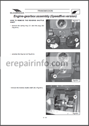
–HOW IT WORKS
GENERAL INTRODUCTION (2 Speed Powershift)
Transmission Access
GENERAL INTRODUCTION (XtraShift)
Trasmission Access
2 SPEED TRANSMISSION DRIVE PATH
Drive Path through the Forward and Reverse Shuttle Transmission
Drive Path through the Four Speed Synchromesh Section
Drive Path through the Two Speed Range Section
MFD Drive Path
PTO Drive Path
XTRASHIFT TRANSMISSION
Drive Path through the XtraShift Transmission
Drive Path through the Four Speed Synchromesh Section
PTO Drive Path
TRANSMISSION LAYOUT
Drive Path through the Differential and Rear Axles
Differential Lock
Service Brakes
Axle Reduction Gears
Rear Axle Half Shafts
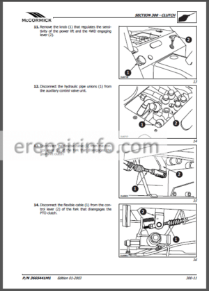
ENGINE CLUTCH (2 Speed Powershift)
General
Engine Clutch Release Bearing
Engine Clutch Control
Engine Flywheel
Clutch Master Cylinder
TWO SPEED POWERSHIFT
General
Fast Speed Selected
Slow Speed Selected
Operation of the Overrun Clutch
FORWARD AND REVERSE SYNCHROMESH SHUTTLE
General
EXTRA SHIFT TRANSMISSION
General
3 Speed Powershift
Forward and Reverse Drive
Forward Drive
Reverse Drive
FOUR SPEED SYNCHROMESH SECTION
General
SECTION 6
SM 8-10201 Issued 07-2006
3
HIGH AND LOW RANGE SECTION
General
Speed Sensor
Park Brake
PTO Drive
MFD Drive
CREEPER SPEED
General
DIFFERENTIAL SECTION
General
Differential Lock
Axle Reduction Gears
Service Brakes
PTO DRIVE (2 Speed Powershift)
General
PTO Drive Speeds
Operation of the PTO Clutch
Hydraulic Pump Drive
PTO DRIVE (XtraShift Transmission)
General
PTO Drive Speeds
Operation of the PTO Clutch
Hydraulic Pump Drive
PTO OPTIONS
Single Speed
Dual Speed
MFD DROPBOX
General
MFD Dropbox Clutch
Park Brake
MFD AXLE
General
Operation of the Limited Slip Differential
–ENGINE CLUTCH, MASTER CYLINDER AND SLAVE CYLINDER
SPECIFICATIONS
SPECIAL TORQUES
TOOLS TO BE MADE
CLUTCH MASTER CYLINDER
Removal and Installation
CLUTCH SLAVE CYLINDER
Removal and Installation
Disassembly and Assembly
REMOVING AIR FROM THE CLUTCH HYDRAULIC SYSTEM
ENGINE CLUTCH AND FLYWHEEL
Removal
Inspection
Cross Sectional Drawing of the Friction Plate
Cross Sectional Drawing of the Pressure Plate, Friction Plate and Flywheel
–2 SPEED POWERSHIFT AND SYNCHRO FORWARD/REVERSE TRANSMISSION SERVICING
SPECIAL TORQUES
SPECIFICATIONS
SPECIAL TOOLS
TOOLS TO BE MADE
POWERSHIFT AND FORWARD/REVERSE TRANSMISSION
Removal
FORWARD/REVERSE SELECTOR FORK COVER
Disassembly and Assembly
FORWARD/REVERSE IDLER GEAR COVER
Disassembly and Assembly
FORWARD/REVERSE SYNCHRONIZER
Disassembly and Assembly
POWERSHIFT CLUTCH
Disassembly
Assembly
Cross Sectional Drawing of the Powershift Clutch Assembly
POWERSHIFT AND FORWARD/REVERSE TRANSMISSION
Installation
Cross Sectional Drawing of the Powershift and Forward/Reverse Transmission
–CREEP TRANSMISSION SERVICING
SPECIFICATIONS
SPECIAL TORQUES
SPECIAL TOOLS
TOOLS TO BE MADE
CREEP TRANSMISSION
Disassembly and Assembly of the Creep Carrier Housing
Removal and Installation of the Creep Mainshaft and Gears
Cross Sectional Drawing of the Creep Carrier Housing
Cross Sectional Drawing of the Creep Mainshaft and Gears
RANGE TRANSMISSION
Disassembly
HIGH/LOW RANGE SYNCHRONIZER
Disassembly and Assembly
CREEP SYNCHRONIZER
Disassembly and Assembly
PINION SHAFT
Inspection and Disassembly
Pinion Shaft Bearing Preload, Mounting Distance and Assembly
RANGE TRANSMISSION
Assembly
Cross Sectional Drawing of the Creep Transmission
–8 SPEED TRANSMISSION SERVICING
SPECIAL TORQUES
SPECIFICATIONS
SPECIAL TOOLS
8 SPEED TRANSMISSION
Removal
FORWARD/REVERSE SELECTOR FORK COVER
Disassembly and Assembly
FORWARD/REVERSE IDLER GEAR COVER
Disassembly and Assembly
FORWARD/REVERSE SYNCHRONIZER
Disassembly and Assembly
8 SPEED TRANSMISSION
Installation
Cross Sectional Drawing of the 8 Speed Transmission
–SYNCHRONIZER SPEED TRANSMISSION SERVICING
SPECIFICATIONS
SPECIAL TORQUES
SPECIAL TOOLS
SPEED TRANSMISSION
SELECTOR FORKS AND RAILS
Removal
Installation
MAIN SHAFT
Removal
Installation
Cross Sectional Drawing of the Main Shaft
COUNTERSHAFT
Removal
Installation
Cross Sectional Drawing of the Countershaft
–RANGE TRANSMISSION SERVICING-2 WHEEL DRIVE TRACTORS
SPECIFICATIONS
SPECIAL TORQUES
SPECIAL TOOLS
TOOLS TO BE MADE
RANGE TRANSMISSION
Disassembly
SYNCHRONIZER
Disassembly and Assembly
PINION SHAFT
Inspection and Disassembly
Pinion Shaft Bearing Preload, Mounting Distance and Assembly
RANGE TRANSMISSION
Assembly
Cross Sectional Drawing of the Range Transmission
–RANGE TRANSMISSION SERVICING-MFD TRACTORS
SPECIFICATIONS
SPECIAL TORQUES
SPECIAL TOOLS
TOOLS TO BE MADE
RANGE TRANSMISSION
Disassembly
SYNCHRONIZER
Disassembly and Assembly
PINION SHAFT
Inspection and Disassembly
Pinion Shaft Bearing Preload, Mounting Distance and Assembly
RANGE TRANSMISSION
Assembly
Cross Sectional Drawing of the MFD Range Transmission
–3 SPEED POWERSHIFT TRANSMISSION SERVICING (XTRASHIFT)
SPECIFICATIONS
SPECIAL TORQUES
SPECIAL TOOLS
TRANSMISSION FRONT COVER
Removal and Installation
Shim setting of Powershift Main shaft and Counter shaft covers
Powershift Main Shaft
Disassembly and Assembly of Reverse Clutch
Powershift Main Shaft
Disassembly and Assembly of nd and Forward Clutch
Cross Sectional Drawing of the Powershift Main Shaft
Powershift Counter Shaft
Disassembly and Assembly
Cross Sectional Drawing of the Counter shaft
–DIFFERENTIAL AND DIFFERENTIAL LOCK
SPECIFICATIONS
SPECIAL TORQUES
DIFFERENTIAL
Removal
Disassembly
Assembly
Positioning the Ring Gear onto the Differential Housing
Cross Sectional Drawing of the Differential
Setting the Differential Bearing Preload
Setting the Ring Gear to Pinion Backlash
DIFFERENTIAL LOCK
Assembly
Cross Sectional Drawing of the Differential Lock
DIFFERENTIAL LOCK SOLENOID
–MFD CLUTCH, TRANSFER GEARBOX, DRIVE SHAFT AND PARKING BRAKE
SPECIFICATIONS
SPECIAL TORQUES
SPECIAL TOOLS
CHECKING THE MFD CLUTCH TORQUE
MFD DRIVE SHAFT
Removal and Installation
MFD TRANSFER GEARBOX
Removal and Installation
Disassembly
MFD CLUTCH
Disassembly and Assembly
MFD TRANSFER GEARBOX
Assembly
Setting the Bearing Preload
Cross Sectional Drawing of the MFD Transfer Gearbox
–REAR AXLES AND PLANETARIES
SPECIFICATIONS
SPECIAL TORQUES
SPECIAL TOOLS
TOOL TO BE MADE
REAR AXLE
Removal and Installation
Disassembly and Assembly
Planetary Gear Disassembly
Planetary Gear Adjustment
Planetary Gear Assembly
Bearing Preload Adjustment
Cross Sectional Drawing of the Rear Axle
–NON SHIFTABLE PTO-CX SERIES TRACTORS
TABLE OF CONTENTS
SPECIFICATIONS
SPECIAL TORQUES
SPECIAL TOOLS
NON SHIFTABLE PTO
Removal and Installation
Disassembly and Assembly
Cross Sectional Drawing of the PTO
PTO CLUTCH
Disassembly and Assembly
Cross Sectional Drawing of the PTO Clutch
–NON SHIFTABLE PTO 2
SPECIFICATIONS
SPECIAL TORQUES
SPECIAL TOOLS
PTO
Removal and Installation
Disassembly and Assembly
Cross Sectional Drawing of the PTO
PTO CLUTCH
Disassembly and Assembly
Cross Sectional Drawing of the PTO Clutch
–SHIFTABLE PTO
TABLE OF CONTENTS
SPECIFICATIONS
SPECIAL TORQUES
TOOL TO BE MADE
SHIFTABLE PTO
Removal and Installation
Disassembly and Assembly
Cross Sectional Drawing of the Shiftable PTO
PTO CLUTCH
Disassembly and Assembly
Cross Sectional Drawing of the PTO Clutch
–SHIFTABLE PTO-CX SERIES TRACTORS
TABLE OF CONTENTS
SPECIFICATIONS
SPECIAL TORQUES
TOOL TO BE MADE
SHIFTABLE PTO
Removal and Installation
Disassembly and Assembly
Cross Sectional Drawing of the Shiftable PTO
PTO CLUTCH
Disassembly and Assembly
Cross Sectional Drawing of the PTO Clutch
–MFD AXLE
SPECIFICATIONS
SPECIAL TORQUES
SPECIAL TOOLS
GENERAL INFORMATION
PLANETARY GEAR
Removal and Installation
Disassembly and Assembly
WHEEL HUB
Disassembly and Assembly
SWIVEL HOUSING
Removal and Installation
Disassembly and Assembly
DRIVE SHAFT
Disassembly and Assembly
CROSS SECTIONAL DRAWING OF THE PLANETARY GEAR ASSEMBLY,WHEEL HUB, SWIVEL HOUSING AND DRIVE SHAFT
MFD AXLE
Removal and Installation
Disassembly and Assembly
DIFFERENTIAL HOUSING
Disassembly
DIFFERENTIAL
Disassembly and Assembly
Cross Sectional Drawing of the Differential
Setting the Position of the Pinion Shaft
Pinion Shaft Assembly
Differential Installation
Ring Gear Backlash Adjustment
Differential Bearing Preload Adjustment
STEERING CYLINDER
Disassembly and Assembly
–FRONT PTO
SPECIFICATIONS
SPECIAL TORQUES
FRONT PTO
Removal and Installation
CX50 and CX60 Tractors
Disassembly and Assembly
Cross Sectional Drawing of the Front PTO
CX70/75, CX80/85, CX90/95 and CX100/105 Tractor
Disassembly and Assembly
Cross Sectional Drawing of the Front PTO
-BRAKES
–HOW IT WORKS
BRAKES
General
BRAKE MASTER CYLINDERS
Brakes Released
One Brake Applied
Both Brakes Applied
Master Cylinders with Trailer Brake Control
BRAKE HOUSINGS
General
Operation
PARKING BRAKE
General
2 Wheel Park Brake
MFD Park Brake
–SERVICE BRAKES
SPECIFICATIONS
SPECIAL TORQUES
SPECIAL TOOLS
TOOLS TO BE MADE
BRAKE DISC
Removal and Installation
BRAKE PISTON
Removal
Installation and Pressure Testing
BRAKE SYSTEM LEAKAGE TEST
MASTER CYLINDER
(Tractors without Hydraulic Trailer Brake Valve)
Removal
Installation
MASTER CYLINDER (Tractors with Hydraulic Trailer Brake Valve)
Removal
Installation
MASTER CYLINDER
Disassembly and Assembly
–PARKING BRAKE-2 WHEEL DRIVE TRACTORS
SPECIFICATIONS
SPECIAL TORQUES
PARKING BRAKE
Removal and Installation
Disassembly and Assembly
Cross Sectional Drawing of the Parking Brake
–HYDRAULIC TRAILER BRAKE
SPECIAL TORQUES
HYDRAULIC TRAILER BRAKE
Removal and Installation
Disassembly and AssemblY
-HYDRAULICS
–HOW IT WORKS
BASIC HYDRAULIC SYSTEM
GENERAL INTRODUCTION
Transfer Pump
Main Hydraulic Pump
Steering Pump
HYDRAULIC SYSTEM SCHEMATICS
Component Description
2 Speed Powershift Schematic
Xtrashift Hydraulic Schematic
Xtrashift Hydraulic Schematic
HYDRAULIC COMPONENT LOCATION
TRANSFER PUMP AND CASCADE SYSTEM
MAIN HYDRAULIC FILTER
Filter Manifold, Gaskets and Seals
STEERING CIRCUIT
Steering Relief Valve
Steering Control Valve
Neutral
LH or RH Steering Operation
Reverse Flow Check Valve
Recirculatory Check Valve
Manual Steering
REGULATOR VALVE BLOCK ( Speed Powershift)
General
Regulated Pressure Valve
POWERSHIFT CLUTCH OPERATION ( Speed Powershift)
General
Fast Speed Selected
Slow Speed Selected
System Testing
REGULATOR VALVE BLOCK (XtraShift
General
Regulated Pressure Valve
FORWARD/REVERSE SHUTTLE (XtraShift)
General
Electronic Control System
Electronic Control Module
Forward and Reverse Solenoids
Operator Clutch Control Potentiometer (Inching Pedal)
3 SPEED POWERSHIFT (XtraShift)
General
Three Speed Powershift Solenoids
Pulse Width Modulation
POWERSHIFT PROPORTIONAL VALVE OPERATION (XtraShift)
Solenoid Off
Solenoid On
XTRASHIFT POWERSHIFT TEST PORTS
REAR PTO (POWER TAKE OFF)
General
Disengaged Position
Initial Engagement
PTO Full Engagement
DIFFERENTIAL LOCK
Differential Lock Engaged
Differential Lock Disengaged
System Testing
MFD (MECHANICAL FRONT DRIVE)
General
Two Wheel Drive
Four Wheel Drive
System testing
OIL COOLER AND LUBRICATION CIRCUIT
General
Oil Cooler and By-pass Valve
Transmission and Brake Lubrication
Brake Reservoir Top Up (Optional)
MAIN HYDRAULIC PUMP
General
MAIN HYDRAULIC CIRCUIT
General
Circuit Flow
MAIN RELIEF VALVE
Relief Valve Operation
Pilot Spool Unseated
Main Spool Unseated
System Testing
TRAILER BRAKE VALVE
General
Brakes Released
Initial Braking
Brake Pressure Equalised
Brake Pressure Limiter
UNLOADER VALVE
General
Hitch Not Raising
Hitch Raising
REMOTE AUXILIARY VALVES
General
Neutral Position
Raise Position
Lower Position
Float Position
Raise and Lower (With Load Check Valves)
Simultaneous Operation
Neutral Return Mechanism (Hydraulic Kickout)
HYDRAULIC POWER BEYOND
General
ELECTRONIC HITCH CONTROL (EHC)
Pulse Width Modulation
Operator Control of the Hitch
Operator Controls
Operating in Position Control
Operating in Load Control (Upper Link Sensing)
HITCH HYDRAULIC CIRCUIT
General
Hitch relief Valve
HITCH CONTROL VALVE
General
Raise and Lower Solenoids
Primary Raise and Lower Spools
Secondary Raise Spool
Secondary Lower Spool
Manual Raise or Lower Control
Hitch in Neutral
Hitch Raising
Hitch Lowering
–HYDRAULIC TROUBLESHOOTING AND SCHEMATICS
SPECIAL TOOLS
SPECIFICATIONS
HYDRAULIC SYSTEM TROUBLESHOOTING
Steering System Problems
Powershift Problems
MFD Problems
PTO Problems
Differential Lock Problems
Oil Cooler Problems
Brake Problems
Hydraulic Trailer Brake Problems (if equipped)
Rear Hitch System Problems
Remote Valve Circuit Problems
HYDRAULIC SYSTEM DIAGNOSTIC TESTING
Test 1 – Main Hydraulic Pump Efficiency
Test 2 – Main Relief Valve
Test 3 – Steering Relief Valve Pressure and Cylinder Internal Leakage
Test 4 – Steering Hydraulic Pump Efficiency
Test 5 – Regulated Pressure
Test 6 – PTO Pressure
Test 7 – Oil Cooler Flow
Test 8 – Regulated Circuit Leakage Test
Test 9 – Remote Detent Kick-out
CROSS SECTIONAL DRAWINGS AND INDIVIDUAL SCHEMATICS
Hydraulic Filter
Main Hydraulic Pump
Filter Manifold
Unloading Valve
Remote Valves
Hitch Valve
EDC Manifold
Hitch Cylinder and Hitch Relief Valve
Steering Hydraulic Pump
Steering Hand Pump
Pressure Regulator Valve Block
MFD Solenoid and Clutch
CX Hydraulic Schematic, Two Speed Power Shift
CX XtraShift, Hydraulic Schematic
CX XtraShift, Hydraulic Schematic
–FILTER MANIFOLD AND MAIN HYDRAULIC PUMP
SPECIFICATIONS
SPECIAL TORQUES
FILTER MANIFOLD
Removal and Installation
Disassembly and Assembly
MAIN HYDRAULIC PUMP
Disassembly and Assembly
CROSS SECTION OF FILTER MANIFOLD AND HYDRAULIC FILTER
CROSS SECTION OF MAIN HYDRAULIC PUMP
–STEERING HYDRAULIC PUMP (ENGINE DRIVEN)
SPECIFICATIONS
SPECIAL TORQUES
STEERING PUMP
Removal and Installation
CX50 and CX60 Tractors
CX70/75, CX80/85, CX90/95 and CX100/105 Tractors
–REGULATOR VALVE
SPECIAL TORQUES
REGULATOR VALVE
Removal and Installation
Disassembly and Assembly
Cross Sectional Drawing of the Regulator Valve
–UNLOADING VALVE
SPECIAL TORQUES
UNLOADING VALVE
Removal and Installation
Disassembly and Assembly
Cross Sectional Drawing of the Unloading Valve
–REMOTE VALVES
SPECIFICATIONS
SPECIAL TORQUES
REMOTE VALV
Removal and Installation
Disassembly and Assembly
REMOTE VALVE WITH NO CHECK VALVES
Disassembly and Assembly
REMOTE VALVE WITH ONE CHECK VALVE
Disassembly and Assembly
REMOTE VALVE WITH TWO CHECK VALVES
Disassembly and Assembly
–HITCH VALVE AND EDC MANIFOLD
SPECIFICATIONS
SPECIAL TORQUES
GENERAL INFORMATION
HITCH VALVE AND EDC MANIFOL
Removal and Installation
Disassembly and Assembly
Cross Sectional Drawing of the Hitch Valve
–HYDRAULIC LIFT HOUSING SERVICING
SPECIAL TORQUES
HYDRAULIC HOUSING
Removal and Installation
Disassembly and Assembly
–FRONT HITCH
SPECIAL TORQUES
FRONT HITCH
Removal and Installation
Disassembly and Assembly
HITCH CYLINDER
Removal and Installation
Disassembly and Assembly
-CHASSIS
–PEDAL, LEVER AND SWITCH ADJUSTMENTS
SPECIAL TOOLS
SPECIAL TORQUES
FORWARD/REVERSE LEVER ADJUSTMENT
Forward Position Switch Setting
BRAKE PEDAL ADJUSTMENT
Brake Pedal Stop Adjustment
Cylinder Rod Adjustment
Brake Pedal Maximum Travel Adjustment
Brake Light Switch Adjustment
PTO ADJUSTMENT
PTO Neutral Start Switch Adjustment
SHIFTABLE PTO ADJUSTMENT
HAND AND FOOT THROTTLE ADJUSTMENT
SPEED/RANGE LINKAGE ADJUSTMENT
st/nd Speed Linkage
rd/th Speed Linkage
Range Linkage
Range Switch Adjustment
CREEP LINKAGE ADJUSTMENT
DIFFERENTIAL LOCK SWITCH ADJUSTMENT
CLUTCH PEDAL ADJUSTMENT (Tractors Without XtraShift)
Clutch Slave Cylinder Rod Adjustment
Clutch Cylinder Rod Adjustment
Interlock Cable Adjustment
Clutch Pedal Position Switch
PARKING BRAKE ADJUSTMENT (MFD)
PARKING BRAKE ADJUSTMENT (WD)
REMOVING AIR FROM THE BRAKE SYSTEM
–CAB MOUNTINGS
SPECIAL TORQUES
SPECIAL TOOLS
CAB MOUNTINGS
Inspection
Removal and Installation
-CONTROL SYSTEM
–HITCH CONTROLLER
SPECIAL TOOLS
TOOLS TO BE MADE
GENERAL INFORMATION FOR ELECTRONIC HITCH CIRCUIT
Hitch Operation
Hitch Electrical Supply and Ground
Hitch Component Supply
HITCH CALIBRATION
GENERAL INFORMATION FOR HITCH ERROR CODES
Normal Operation
No Error Codes Displayed But Hitch Is Not Working Correctly
Diagnostic Display is Blank
Failure Modes
General Notes
Error Codes That Disable Hitch Motion
Other Possible Error Indications
Error Codes That Allow Hitch Operation
Failures That Are Checked Once
Double Failures Involving The UP/DOWN Switch
CALIBRATION ERROR CODE CHART
READING AND ERASING ERROR CODES
HITCH SYSTEM PERFORMANCE CODE CHART
CIRCUIT TESTING
General Information
Hitch Operating Circuit
Test 1 – No Power to Controller (Power and Clean Ground)
Test 2 – Circuit Shorted to Ground
Test 3 – Hitch Up/Down Switch and Hitch Enable Lamp
Test 4 – Hitch Up/Down Switch Circuit
Test 5 – Hitch Enable Relay Circuit
Test 6 – Hitch Solenoids Circuit
Test 7 – R/H Hitch Remote Switch
Test 8 – L/H Hitch Remote Switch
Hitch Position Control Circuit
Test 9 – Hitch Position Potentiometer
Test 10 – Hitch Position Command Potentiometer
Test 11 – Hitch Drop Speed Potentiometer
Test 12 – Hitch Upper Height Potentiometer
Hitch Load Control Circuit
Test 13 – Load Pin
Test 14 – Hitch Load Command Potentiometer
Test 15 – Hitch Travel Potentiometer
Test 16 – Hitch Response Potentiometer
Test 17 – Wheel Speed Sensor
HARNESS LAYOUT, SCHEMATICS AND CONNECTORS
Right Hand Console Harness Components
Transmission and Rear Fender Harness Components
Hitch Control Schematic Circuit
Schematic Legend
Wire Colour Code
Main Connectors
–HITCH/MFD/DIFFERENTIAL LOCK CONTROLLER
SPECIAL TOOLS
TOOLS TO BE MADE
DELUXE HITCH CALIBRATION
Tire Size Calibration and Ride Control Enabling/Disabling
GENERAL INFORMATION FOR HITCH ERROR CODES
Normal Operation
No Error Codes Displayed But Hitch Is Not Working Correctly
Controller LED
Failure Modes
General Notes
Error Codes That Disable Hitch Motion
Other Possible Error Indications
Error Codes That Allow Hitch Operation
Failures That Are Checked Once
Double Failures Involving The UP/DOWN Switch
CALIBRATION ERROR CODE CHART
READING AND ERASING ERROR CODES
HITCH SYSTEM PERFORMANCE CODE CHART
CIRCUIT TESTING
General Information
Hitch Operating Circuit
Test 1 – No Power to Controller (Power and Clean Ground)
Test 2 – Circuit Shorted to Ground
Test 3 – Hitch Up/Down Switch and Hitch Enable Lamp
Test 4 – Hitch Up/Down Switch Circuit
Test 5 – Hitch Solenoids Circuit
Test 6 – R/H Hitch Remote Switch
Test 7 – L/H Hitch Remote Switch
Hitch Position Control Circuit
Test 8 – Hitch Position Potentiometer
Test 9 – Hitch Position Command Potentiometer
Test 10 – Hitch Drop Speed Potentiometer
Test 11 – Hitch Upper Height Potentiometer
Hitch Load Control Circuit
Test 12 – Load Pin
Test 13 – Hitch Load Command Potentiometer
Test 14 – Hitch Travel Potentiometer
Test 15 – Wheel Speed Sensor
Slip Limit Control Circuit
Test 16 – Slip Control Switch
Test 17 – Slip Control Switch Circuit
Test 18 – Radar
Ride Control Circui
Test 19 – Ride Control Switch
Differential Lock Circuit
Test 20 – Differential Lock Solenoid
Test 21 – Differential Lock Switch, Auto Differential and Auto Indicator Lamp
Test 22 – Differential Lock Warning Lamp and Switch
MFD Circuit
Test 23 – MFD Solenoid
Test 24 – MFD Switch and Auto MFD Circuit
Test 25 – MFD Relay Circuit
Test 26 – MFD Indicator Lamp
Brake Switches
Test 27
HARNESS LAYOUT, SCHEMATICS AND CONNECTORS
Instrument Panel Components
Right Hand Console Harness Components
Transmission Harness and Fender Harness Components
Hitch Control Schematic Circuit
Differential Lock and MFD Schematic Circuit
Schematic Symbols
Schematic Legend
Wire Colour Code
Main Connectors
TIRE RADIUS CONSTANT TABLE
–TRANSMISSION CONTROLLER, F/N/R AND POWERSHIFT
SPECIAL TOOLS
ELECTRONIC TRANSMISSION CONTROL
Transmission Control Functions
Controller LED’s
Error Codes
Operators Seat Switch Monitor, Park Brake and Alarm
CALIBRATION
Calibration Procedure – Method 1 (New Controller)
Calibration Procedure – Method 2 (Existing Controller Recalibration)
Tyre Radius Constant Table
INCHING PEDAL POTENTIOMETER ADJUSTMENT
ERROR CODES
General Information
Retrieving and Identifying Error Codes
Error Code Quick Reference Guide
TROUBLESHOOTING GUIDE
Circuit Testing General Information
Error Code 20/19
Error Code 22/12
Error Code 22/15
Error Code 24/12
Error Code 24/15
Error Code 25/11 & 12
Error Code 25/15 & 16
Error Code 26/12
Error Code 26/15
Error Code 28/12
Error Code 28/15
Error Code 37/23
Error Code 37/24
Error Code 37/25
Multi Error Codes 22/12, 24/12 and 25/11 & 12
Multi Error Codes 22/15, 24/15 and 25/15 & 16
No Error Code
Controller LED’S not Illuminated
No Error Code
No Forward Drive
No Error Code
No Reverse Drive
No Error Code
No Forward or Reverse Drive
No Error Code
Return to Neutral Light on when Forward or Reverse Selected
No Error Code
No Drive in 1st Speed Powershift
No Error Code
No Drive in 2nd Speed Powershift
No Error Code
No Drive in 3rd Speed Powershift
No Error Code
No Drive in 1st, 2nd or 3rd Speed Powershift
No Error Code
Defaults to 1st Speed Powershift 1 when 2nd Speed Powershift Selected
No Error Code
Defaults to 3rd Speed Powershift 3 when 1st and 2nd Speed
Powershift Selected
HARNESS LAYOUT AND CHASSIS GROUND LOCATION
Instrument Panel Harness Components – Tractors Without Ride Control
Instrument Panel Harness Components – Tractors With Ride Control
Right Hand Console Harness Components – Tractors Without Ride Control
Right Hand Console Harness Components – Tractors With Ride Control
Transmission Harness Components
SCHEMATIC CIRCUIT
MAIN CONNECTORS
–PROGRAMMING HITCH/MFD/DIFFERENTIAL LOCK CONTROLLER
SPECIAL TOOLS
GENERAL INFORMATION
CONTROLLER PROGRAMMING
What you get
You will receive PDF file with high-quality manual on your email immediately after the payment.


Anonymous (verified owner) –
Wery good!
Anonymous (verified owner) –
Easy to download