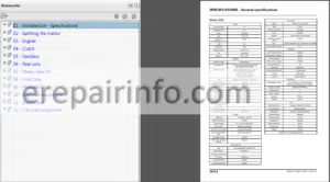
Factory Service Repair Manual For Massey Ferguson 3600 Series Tractors. Tons of illustrations, instructions, diagrams for step by step remove and install, assembly and disassembly, service, inspection, repair, troubleshooting, tune-ups.
Format: PDF
Language: English
Pages: 762
Bookmarks: Yes
Searchable: Yes
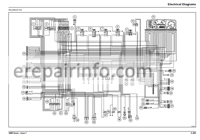
Wiring Diagrams: Yes
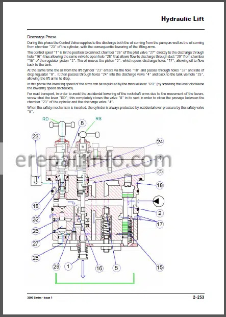
Hydraulic Diagrams: Yes
Model
Massey Ferguson 3600 Series
Contents
- -INTRODUCTION AND SAFETY IN THE WORKSHOP
Introduction
Safety Alert Symbol And Terms
Safety In The Workshop
Safety – A Word To The Mechanic
Safety – Danger Warning And Caution
Safety Decals
General
Personal Considerations
Equipment Considerations
General Considerations
Operational Considerations
Servicing Techniques - -Tractor
–General information
MANUAL USE
Maintenance
Repair
Information Property
AGREEMENTS AND DEFINITIONS
Agreements
Definitions
Typographic Agreements
Measurements
Symbology
GENERAL DESCRIPTION
General
Hoses And Tubes
O-Ring Flat Face Seal Fittings
Shimming
Rotating Shaft Seals
O-Rings
Bearings
Spring Pins
Hardware Torque Values
Notes For Spare Parts
Notes For Equipment
Notices
How To Move The Machine With The Battery Removed
–General Specification
Product Identification
Cab
Platform Tractors
Platform Tractors
General Description
Tare Weights Kg (Lb)*
Max Permissible Weights Kg (Lb)
Tare Weights Kg (Lb)*
Max Permissible Weights Kg (Lb)
Dimensions With Platform
Dimensions With Cab
Steering Angle
Steering Radius
Travel Speed
Tyre
Tyre Pressure
Battery
Description And Operation
Battery Replacement
Maintenance
Servicing
Dry Charged
Charging The Battery
Normal (Top-Up) Charging
Recharging Deeply Discharged
Tests
Specific Gravity
Performance Test
Test Charging
Common Causes Of Battery Failures
Emergency Starting Through Another Battery
Battery Connection Using Suitable Cables
Alternator
General Maintenance Table
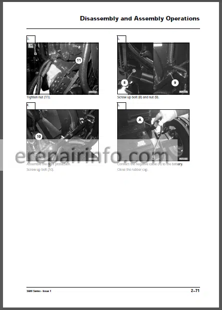
–DISASSEMBLY AND ASSEMBLY OPERATIONS
Air Filter
Air Filter Line
Battery
Alternator
Radiator
Fan
Exhaust Pipe
Fan Belt
Air Filter Assy Replacement
Bonnet
Front Weight
Oil Cooler
Muffler
Hydraulic Pump
Starting Motor
Engine Removal
Front Axle Wd
Fuel Tank
Brake Cylinder
Hand Brake Adjustment
Lock Valve
Rockshaft Valve
Rear Wheels
Auxiliary Distributors
Oil Suction Strainer
Oil Filter Cartridge Replacement
Side Auxiliary Distributors
Powershuttle Hydraulic Valve
Oil Filter Sensor
Clutch Box
Rockshaft
Platform
Steering Valve
Brake Circuit Bleeding - -Electrical System
–Electrical Diagrams
Colour Abbreviation
Hi-Lo Power Harness
Hi-Lo Power Harness
Trailer Brake Valve Italy Harness
Trailer Brake Valve Italy Harness
Massey Ferguson Bonnet Line
Massey Ferguson Bonnet Line
A/C Power Harness
A/C Power Harness
Preheating Harness
Preheating Harness
Mf Engine Line
Mf Engine Line
Na Platform Line
Na Platform Line
Row Platform Line
Row Platform Line
V Powershuttle Harness
V Powershuttle Harness
Cab Electric System
Powershuttle Line - -Hydraulic System
–Hydraulic System Components
Major Components
–Hydraulic Lift
SPECIFICATIONS
Technical Features
Dimensional Features
Calibration Settings Of Control Valve
DIAGRAM
CIRCUIT DIAGRAM OF HYDRAULIC LIFTING DEVICE
FUNCTIONING OF CONTROL VALVE
Neutral Phase
Delivery Phase
Discharge Phase
HOW THE INTERNAL LEVERAGE SYSTEM FUNCTIONS
Functioning With Position Control (Fig Page 52)
Functioning Of Draft Control (Fig Page 52 – 54)
Combined Functioning Of Position And Draft Control (Fig Page 52-54)
USE OF CONTROL LEVERS
Position Control (Lever 1)
Draft Control (Lever 2)
Combined Operation For Position And Draft Control
ADJUSTMENT OF CONTROL VALVE SENSITIVITY
Functioning Of The Sensitivity Of The Control Valve
ADJUSTMENT OF POSITION CONTROL LEVER
ADJUSTMENT OF DRAFT CONTROL LEVER
CONTROL OF ASSEMBLY OF REACTION SPRING
MEASUREMENT CONTROL OF PUSH ROD
DIAGNOSTIC
–DIFFERENTIAL ASSEMBLY
Disassembly
Assembly - -TRANSMISSION 506 HTR
Intended Use
Product Identification
Technical Features
Tightening Torques, Sealants And Grease Application
Hi/Lo Power Flows
Assembly Typical Data
Filling And Checks
Service Schedule
–DISASSEMBLY AND ASSEMBLY OPERATIONS
Hydraulic System Assy
Drop Box
Final Drive – From 55 To 75 Hp
Final Drive – 85 Hp
Teflon Seals Replacement (Clutch Shaft)
Input Shaft And Support
Upper Covers And Rockshaft
Speed And Ranges Levers
Clutch Housing – Synchro Shuttle
Clutch Housing – Synchro Splitter
Synchro Shuttle And Power Splitter
Power Shuttle – Power Shuttle And Synchro Splitter
Air Compressor
Wet Clutch – Power Splitter
Wet Clutch – Power Shuttle
Hi-Lo Synchronizer (Synchro Splitter)
Cover And Pto Wet Clutch
Pto – Power Take Off
Pto Input Shaft
Pto Output Shaft
Pto Brake
Ground Drive Pto
Slave Cylinder
Parking Brake
Housing Sensors Assy
Differential Locking Control
Inner Control Assy
Idle Gear
Power Shuttle
Range Gears (Primary Shaft)
Input Shaft – Synchro Shuttle
Input Shaft – 12+12 Power Shuttle
Synchronizer Shuttle (Replacement)
Speed Gears (Primary Shaft)
Differential Assy
Pinion – Ranges Pinion – Ranges (Secondary Shaft)
Secondary Shaft
Speed Gears (Secondary Shaft)
–Special Tools
SPECIAL TOOLS
Drop Box
Gear Box
Clutch Housing (12+12 Power Shuttle)
Wet Clutch (Power Shuttle)
Wet Clutch (Power Splitter)
Final Drive – From 55 To 75 Hp
Final Drive – 85 Hp
Clutch Housing (Synchro Shuttle – Synchro Splitter
Cover And Pto Wet Clutch
Clutch Housing (Synchro Shuttle – Synchro Splitter
Clutch Housing (Synchro Shuttle And Power Splitter)
Clutch Housing (Synchro Shuttle) - -2WD AXLE
–General Information
MANUAL USE
Maintenance
Repair
INFORMATION PROPERTY
AGREEMENTS AND DEFINITIONS
Agreements
Definitions
Typographic Agreements
Measurements
Conversion Table
Symbology
GENERAL DESCRIPTION
RECOMMENDATIONS FOR REPAIR OPERATIONS
Shafts Seals
O-Rings
Bearings
Sealing
Cleaning
Checks
Ends Of Flanges And Tools
Assembly Methods
–Genral Specifications
INTENDED USE
PRODUCT IDENTIFICATION
Axle Tag
GENERAL DESCRIPTION
TECHNICAL FEATURES
Main Dimensions (Mm)
MAINTENANCE
Service Schedule
Lubricants Application Range
GREASE IN ASSEMBLY
ADHESIVE AND SEALANT
Sealing Compounds And Adhesives
TIGHTENING TORQUES
–DISASSEMBLY AND ASSEMBLY OPERATIONS
STEERING CYLINDER GROUP
Disassembly
Assembly
WHEEL HUB GROUP
Disassembly
Assembly
WHEEL HUB SUPPORT GROUP
Disassembly
Assembly
AXLE BEAM GROUP
Disassembly
Assembly
TOE-IN/STEERING ANGLE
Toe-In Adjustment
Steering Angle Adjustment
–Troubleshooting
Troubleshooting
Axle Problem And Diagnosis - -Front Axle
–General Information
MANUAL USE
Maintenance
Repair
INFORMATION PROPERTY
AGREEMENTS AND DEFINITIONS
Agreements
Definitions
Typographic Agreements
Measurements
Conversion Table
Symbology
GENERAL DESCRIPTION
RECOMMENDATIONS FOR REPAIR OPERATIONS
Shafts Seals
O-Rings
Adjusting Shims
Bearings
Split Pins
Sealing
Oil Drain
Cleaning
Checks
Ends Of Flanges And Tools
Lubricant Use
–General Specifications
INTENDED USE
PRODUCT IDENTIFICATION
Axle Serial Plate
GENERAL DESCRIPTION
TECHNICAL FEATURES
Limited Slip Differential Disks Specifications
Principal Dimensions (Mm)
MAINTENANCE AND OIL CHANGE
Service Schedule
Lubricants Application Range
GREASE IN ASSEMBLY
ADHESIVE AND SEALANT
Sealing Compounds And Adhesives
TIGHTENING TORQUES
–DISASSEMBLY AND ASSEMBLY OPERATIONS
STEERING CYLINDER GROUP
Disassembly
Assembly
EPICYCLIC REDUCTION GEAR GROUP
Disassembly
Assembly
WHEEL HUB GROUP
Disassembly
Assembly
AXLE BEAM GROUP
Disassembly
Assembly
TRUNNIONS GROUP
Disassembly
Assembly
DIFFERENTIAL SUPPORT GROUP
Disassembly
Assembly
BEVEL GEAR MARKING TEST
DIFFERENTIAL GROUP
Disassembly
Assembly
PINION GROUP
Disassembly
Assembly
TOE-IN/STEERING ANGLE
Toe-In Adjustment
Steering Angle Adjustment
SPECIAL REPAIR OPERATIONS
Wheel And Double U-Joint Group Disassembly
Wheel And Double U-Joint Group Assembly
Double U-Joint Seal Ring Replacement On Axle Beam Side
Double U-Joint Bushing Replacement On Axle Beam Side
TESTING AFTER ASSEMBLY
Testing Methods
–Troubleshooting
Troubleshooting
Axle Problem And Diagnosis
–SPECIAL TOLLS
–SERVICE OPERATIONS TIME
SERVICE OPERATIONS TIME SCHEDULE
Steering Cylinder Group (G3)
Epicyclic Reduction Gear Group (G1)
Wheel Hub Group (G1)
Axle Beam Group (G4)
Trunnions Group (G2-G4)
Differential Support Group (G2)
Differential Group (G2)
Pinion Group
What you get
You will receive PDF file with high-quality manual on your email immediately after the payment.


Reviews
There are no reviews yet.