


Factory Service Manual For Mitsubishi D04FD-TAA Diesel Engine. Tons of illustrations, instructions, diagrams for step by step remove and install, assembly and disassembly, service, inspection, repair, troubleshooting, tune-ups.
Format: PDF
Language: English
Pages: 252
Wiring Diagrams: Yes
Model
Mitsubishi D04FD-TAA
Contents
-GENERAL
–Outline Drawings
D04Fd-Taa Outline Drawings
–System Flow
Fuel Flow
Oil Flow
Cooling Water Flow
Inlet And Exhaust Flow
Electrical Wiring Diagram
–Engine Serial Number Location
Main Specifications
Tips On Disassembling And Reassembling
Disassembling
Reassembling
-SERVICE DATA
–Maintenance Service Data
Engine General
Engine Main Part
Lubrication System
Cooling System
Inlet And Exhaust System
Electrical System
–List Of Tightening Torque
Major Bolts And Nuts Tightening Torque
Basic Engine
Fuel System
Lubrication System
Inlet And Exhaust System
Electrical System
Sensors And Ecm
Standard Bolt And Nut Tightening Torque
Standard Eyebolt Tightening Torque
Standard Union Nut Tightening Torque
-BASIC AND SPECIAL TOOLS
Special Tools
-OVERHAUL INSTRUCTIONS
Determining Overhaul Timing
Testing Compression Pressure
-DISASSEMBLING ENGINE MAIN PARTS
–Disassembling And Inspecting Cylinder
Head And Valve Mechanism
Removing Harness
Removing Injector
Removing Rocker Case
Hemovmg Rocker Snatt Assembly
Disassembling Rocker Shaft Assembly
Removing Valve Bridge
Removing Cylinder Head Bolt
Removing Cylinder Head Assembly
Removing Valves And Valve Springs
Removing Valve Stem Seal
Bridge Guide
Installing Bridge Guide
–Disassembling And Inspecting
Flywheel
Removing Flywheel
Removing Flywheel Housing
–Disassembling And Inspecting Gear Case, Timing Gear And Camshaft
Removing Crankshaft Pulley
Removing Timing Gear Case
Measuring Backlash Of Timing Gears
Measuring Idler Gear End Play
Removing Idler Gear
Removing Camshaft
Separating Camshaft Gear
Installing Camshaft Gear And Thrust Plate
Removing Front Plate
–Disassembling And Inspection Crankcase, Crankshaft And Piston
Removing Connecting Rod Cap
Removing Carbon Deposit From Cylinder Sleeve Upper Area
Pulling Out Piston
Removing Piston Ring
Removing Piston Pin
Removing Main Bearing Cap
Removing Crankshaft
-INSPECTING AND REPAIRING ENGINE MAIN PARTS
–Inspecting And Repairing Cylinder Head And Valve Mechanism
Measuring Clearance Between Rocker Bushing And Rocker Shaft
Replacing Rocker Bushing
Measuring Valve Stem Outside Diameter And Valve Guide Inside Diameter
Replacing Valve Guide
Inspecting Valve Face
Refacing Valve Face
Refacing Valve Seat
Replacing Valve Seat
Lapping Valve And Valve Seat
Measuring Perpendicularity And Free Length Of Valve Spring
Measuring Distortion Of Cylinder Head Bottom Face
Measuring Pushrod Runout
–Inspecting And Repairing Flywheel
Measuring Flatness Of Flywheel
Measuring Flywheel Face Runout And Radial Runout
Inspecting Ring Gear
Replacing Ring Gear
Removing Ring Gear
Installing Ring Gear
–Inspecting And Repairing Timing Gears And Camshaft
Measuring Backlash Of Timing Gear
Measuring Cam Lift
Measuring Camshaft Runout
Measuring Camshaft Journal Outside Diameter
Measuring Camshaft Bushing Inside Diameter
Replacing Camshaft Bushing
Removing Camshaft Bushing
Installing Camshaft Bushing
Measuring Idler Bushing Inside Diameter And Idler Shaft Outside Diameter
Replacing Idler Bushing
Replacing Idler Shaft
Inspecting Tappet
Measuring Clearance Between Tappet And Tappet Guide Hole
–Inspecting And Repairing Piston, Connecting Rod, Crankshaft And Crankcase
Measuring Distortion Of Crankcase Top Surface
Measuring Cylinder Inside Diameter
Replacing Cylinder Sleeve
Removing Cylinder Sleeve
Installing Cylinder Sleeve
Measuring Piston Outside Diameter
Measuring Piston Ring End Gap
Measuring Clearance Between Piston Ring Groove And Piston Ring
Measuring Piston Pin Bore Diameter And Piston Pin Outside Diameter
Measuring Piston Protrusion
Measuring Clearance Between Connecting Rod Bearing And Crankpin
Measuring Clearance Between Connecting Rod Bushing And Piston Pin
Replacing Connecting Rod Bushing
Removing Connecting Rod Bushing
Installing Connecting Rod Bushing
Inspecting Connecting Rod Bend And Twist
Inspecting Connecting Rod Beanng
Measuring Connecting Rod End Play
Weight Difference Of Connecting Rod Assembly In One Engine
Measuring Crankshaft Journal Outside Diameter
Measuring Crankshaft Crankpin Outside Diameter
Grinding Crankshaft
Measuring Crankshaft End Play
Measuring Crankshaft Runout
Replacing Crankshaft Gear
Removing Crankshaft Gear
Installing Crankshaft Gear
Replacing Front Oil Seal
Replacing Rear Oil Seal
Inspecting Main Bearing Surface
Measuring Clearance Between Main Bearing And Crankshaft Journal
-REASSEMBLING ENGINE MAIN PARTS
–Reassembling Piston, Connecting Rod, Crankshaft And Crankcase
Installing Main Bearing
Installing Th Rust Plate
Installing Crankshaft
Installing Mam Bearingcaps
Inserting Side Seal
Installing Main Bearingcap Bolt
Measuring Crankshaft End Play
Reassembling Piston And Connecting Rod
Installing Piston Ring
Preparation For Installing Pistons
Installing Connecting Rod Bolt And Connecting Rod Bearing
Installing Pistons
Installing Connecting Rod Cap
–Reassembling Timing Gear And Camshaft
Installingfront Plate
Installingtappet
Installingcamshaft
Installingidler Gear
Inspecting And Adjusting Timing Gear After Installation
Inspecting Backlash And End Play
Installing Front Oil Seal
Installing Timing Gear Case
Installing Crankshaft Pulley
–Reassembling Flywheel
Installing Flywheel Housing
Installing Flywheel
–Reassembling Cylinder Head And Valve Mechanism
Cleaning Cylinder Head Bottom Surface
Installing Valve Stem Seal
Installing Valve And Valve Spring
Installing Cylinder Head Gasket
Installing Cylinder Head Assembly
Tightening Cylinder Head Bolts
Inserting Pushrod
Reassembling Rocker Shaft Assembly
Installingrocker Shaft Assembly
Installingrocker Case
Installinghamesse
Installinginjector
Adjusting Valve Clearance
Installing Rocker Cover
-FUEL SYSTEM
–Removing Fuel System
Removing Fuel System (Part 1)
Removing Fuel System (Part 2)
–Assembling Fuel System
Installing Fuel Filter
–Installing Fuel System
Installing Fuel System (Part 1)
Installing Fuel System (Part 2)
Replacing Fuel Pump
Removing Fuel Pump
Replacing Fue Fuel Pump Gear
Installing Fuel Pump
-LUBRICATION SYSTEM
–Removing And Inspecting Lubrication System
–Disassembling, Inspecting And Reassembling Lubrication System
Disassembling And Inspecting Oil Pump
Removing Oil Pump Gear
Removing Spindle And Idler Gear
Inspecting And Adjusting Oil Pump
Measuring End Clearance Between Gears And Case
Measuring Side Clearance Between Gears And Case
Measuring Clearance Between Outside Diameter Of Gear Shaft And Inside Diameters Of Pump Body And Pump Cover
Measuring Spindle Outside Diameter And Idler Bushing Insidediameter
Reassembling Oil Pump
Reassembling Oil Pump Gear And Drive Gear Assembly
Inspecting Oil Filter
Inspecting Relief Valve
Inspecting Safety Valve
–Installing Lubrication System
-COOLING SYSTEM
–Removing Cooling System
–Disassembling, Inspecting And Reassembling Cooling System
Disassembling And Inspecting Water Pump
Removing Flange
Removing Impeller And Shaft
Inspecting Unit Seal
Inspecting Water Pump Shaft
Inspecting Water Pump
Reassembling Water Pump
Installing Unit Seal
Checking Water Pump For Smooth Rotation
Inspecting Thermostat
–Installing Cooling System
-INLET AND EXHAUST SYSTEM
–Removing Inlet And Exhaust System
Removing Inlet System
Removing Exhaust System
–Disassembling, Inspecting And Reassembling Inlet And Exhaust Systeml
Measuring Exhaust Manifold Distortion
–Installing Inlet And Exhaust Systeml
Installing Inlet System
Installing Exhaust System
-ELECTRICAL SYSTEM
–Removing Electrical System
Removing Starter
Inspection Before Removing Alternator
Inspecting Alternator Operation
Handling Precaution
Reiiroviny Alternator
–Disassembling, Inspecting And Reassembling Electrical System
Inspection Before Disassembling Starter
Inspecting Magnet Switch
No Load Test
Disassembling And Inspecting Starter
Removing Pinion Set
Removing Magnet Switch
Removing Brush Holder And Brush Assembly
Removing Rear Bracket
Removing Armature And Yoke
Removing Overrunning Clutch
Inspecting And Repairing Starter
Inspecting Brushes For Wear
Measuring Brush Spring Load
Inspecting Brush Holder For Insulation
Inspecting Commutator Radial Runout
Measuring Commutator Outside Diameter
Measuring Undercut Depth
Checking Armature Coil
Inspecting Rear Bracket
Inspecting Overrunning Clutch
Inspecting Front Bracket
Inspecting Gears Of Starter
Inspecting Continuity Of Magnet Switch (Between M Terminal And Case)
Inspecting Insulation Of Magnet Switch (Between M Terminal And ? Terminal)
Reassembling Starter
Installing Gear Shaft
Installing Pinion
Installing Yoke And Armature
Installing Brush Holder And Brush Assembly
Disassembling And Inspecting Alternator
Separating Front Bracket From Stator
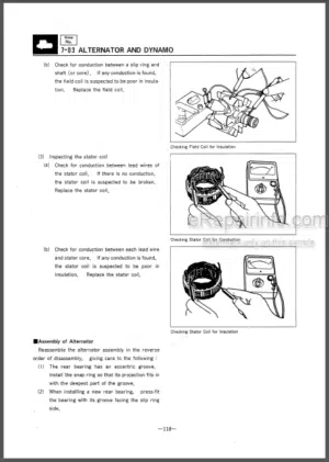
Removing Field Coil
Removing Pulley
Removing Rear Bearing
Removing Front Bearing
Removing Stator
Removing Regulator Assembly
Removing Rectifier Assembly
Inspecting And Repairing Alternator
Inspecting Stator
Inspecting Rectifier
Measuring Field Coll
Reassembling Alternator
Installing Rectifier Assembly And Regulator Assembly
Installing Stator
Installing Front Bearing
Installing Rear Bearing
Installing Pulley
Assembling Stator And Front Bracket
Inspecting Air Beater
–Installing Electrical System
Installing Starter
Installing Alternator
Installing Various Sensors
-ENGINE ADJUSTMENT, BREAK-IN OPERATION AND PERFORMANCE TEST
–Adjusting Engine
Inspecting And Adjusting Valve Clearance
Adjusting Front And Rear Valve Heights By Valve Bridge
Inspecting Valve Clearance
Adjusting Valve Clearance
Bleeding Fuel System
Bleeding Fuel Filter
–Breakin Operation
Starting Up
Inspecting Engine Condition After Starting Up
Breakin Operation Time
Inspection And Adjustment After Breakin Operation
–Performance Test (Jis Standard)
Engine Equipment Condition
Test Items And Purposes
Operation Load Test
Continuous Load Test
Low Idle Test
Other Inspections
Engine Output Adjustment
Standard Atmospheric Conditions
Calculation Of Corrected Power
-TROUBLESHOOTING
–Electronic Troubleshooting
System Overview
Engine Speed Governor
Timing Considerations
Fuel Injection
Diagnostic
Event
Programmable Parameters
Passwords
Replacing The Ecm
Selfdiagnostics
Diagnostic Code
Event Code
Ecm Harness Connector Terminals
Harness Connector Terminal Removal
Harness Connector Terminal Insertion
–Programming Parameters
Programming Parameters
Test Ecm Mode
Ecm Snapshot
Snapshot That Is Triggered By A Diagnostic Code
Snapshot That Is Triggered By The Operator
Use Of Snapshot Data
Factory Passwords
Factory Passwords Worksheet
Flash Programming
Rash Programming A Flash File
‘Winflash’ Error Messages
Injector Trim File
–System Configuration Parameters
System Configuration Parameters
“Full Load Setting”
“Full Torque Setting”
“Rating Interlock”
“Engine Serial Number”
“Ecm Software Release Date”
–Troubleshooting Without Diagnostic Code
Ecm Will Not Accept Factory Passwords
Probable Causes
Recommended Actions
Ecm Will Not Communicate With Other Systems Or Display Modules
Probable Causes
Recommended Actions
Electronic Service Tool Will Not Communicate With Ecm
Probable Causes
Recommended Actions
Configuration For The Communications Adapter
Electrical Connectors
Communication Adapter And’or Cables
Electrical Power Supply To The Service Tool Connector
Mitsubishi Et And Related Hardware
Electrical Power Supply To The Ecm
Flash Tilo
Conventional Data Link
–Troubleshooting With A Diagnostic Code
Diagnostic Code Cross Reference
Injector Data Incorrect (Code J65X-2)
Injector Open Circuit (Code J65X-5)
Injector Short (Code J65X-6)
Injector Not Responding (Code J65X-7)
8 Volt Dc Supply Short To +Batt(Code J678-03)
8 Volt Dc Supply Short To Ground(Code J678-04)
Accelerator Pedal -Voltage Above Normal(Code J91-03)
Accelerator Pedal -Voltage Below Normal(Code J91-04)
Throttle Position Signal Abnormal(Code J91-08)
Engine Oil Pressure Open/Short To +Batt(Code J100-03)
Engine Oil Pressure Short To Ground(Code J100-04)
Engine Oil Pressure Sensor Abnormal Rate Ofchange (Code J100-10)
Engine Coolant Temperature Open/Short To+Batt (Code J110-03)
Engine Coolant Temperature Short To Ground(Code J110-04)
System Voltage High (Code J168-O0)
System Voltage Low (Code J168-01)
System Voltage Intermittent/Erratic(Code J168-02)
Inlet Manifold Air Temp Open/Short To +Batt(Code J105-03)
Inlet Manifold Air Temp Short To Ground(Code J105-04)
Engine Speed Signal Abnormal(Code J190-08)
J1939 Data Link Communications(Code J639-09)
Personality Module Mismatch(Code J631-02)
Speedrtiming Sensor Offset Fault(Code J637-11)
5 Volt Sensor Dc Power Supply Short To +Batt(Code J1079-03)
5 Volt Sensor Dc Power Supply Short To Ground (Code J 079-04)
Check Programmable Parameters(Code J630-02)
Fuel Pump Side Engine Speed Signal Abnormal(Code J723-08)
Engine Mode Selection Switch Slate Incorrect(Code J2882-02)
Fuel Pump Solenoid Open Circuit(Code J1347-05)
Fuel Pump Solenoid Short To Ground(Code J1347-06)
Inlet Manifold Pressure Sensor Voltage High(Code J102-03)
Inlet Manifold Pressure Sensor Voltage Low(Code J102-04)
Common Rail Pressure Sensor Open/Short To+Batt (Code J157-03)
Common Rail Pressure Sensor Short To Ground(Code J157-04)
Ignition Key Switch Loss Of Signal (Code J158-02)
–Troubleshooting with an eventcode
Outline of event codes
Low engine oil pressure(code J100-01,17)
High engine coolant temperature (code J110-0015 16)
Engine overspeed (code J190-15)
High common rail pressure(code J157-00)
Low common rail pressure(code J157-01)
High inlet manifold air temperature (code J105-15,16)
–Diagnostic Functional Tests
5 Volt Sensor Supply Circuit-Test
Test Step 1 Check For Connector Damage
Test Step 2 Check For Active Diagnostic Codes
Test Step 3 Disconnect The Sensors
Test Step 4 Install A New Sensor
Test Step 5 Disconnect The Ecm Connector And Check For Active Diagnostic Codes
Test Step 6 Check The *5 Volt Supply Wire For A Short To Engne Ground Or A Short To Other Wires In The Harness
Test Step 7 Measure The *5 Volt Supply To The Sensor
Test Step 8 Check The Ground Wire
Analog Throttle Position Sensor Circuit -Test
Test Step 1 Check For Connector Damage
Test Step 2 Check For Active Diagnostic Codes
Test Step 3 Check The Throttle Position With The Mitsubishi Et
Test Step 4 Check The Voltage At The Sensor
Test Step 5 Check The Position Of Sensor
Test Step 6 Check The Sensor At The Ecm
Test Step 7 Remove The Sensor From The Engine Speed Control Assembly
Can Data Link Circuit-Test
Test Step 1 Inspect Electrical Connectors
Test Step 2 Check The Data Link Terminating Resistance
Test Step 3 Check The Data Link Wiring 14-37
Test Step 4 Check The Other Devices On The J1939 Data Link
Conventional Data Link Circuit-Test14-37
Test Step 1 Inspect Electrical Connectors And Wiring
Test Step 2 Determine The Type Of Problem With The Conventional Data Link
Test Step 3 Check The Wiring Of The Diagnostic Connector
Test Step 4 Check The Battery Voltage At The Diagnostic Connector
Test Step 5 Check The Data Link Connections
Test Step 6 Change The Mitsubishi Et Components
Test Step 7 Connect A Mitsubishi Et And The Ecm To Another Battery
Ecm Memory-Test
Electrical Connectors-Inspect
Test Step 1 Check Connectors For Moisture And Corrosion
Test Step 2 Check The Wires For Damage To The Insulation
Test Step 3 Inspect The Connector Terminals
Test Step 4 Perform A Pull Test On Each Wire Terminal Connection
Test Step 5 Check Individual Pin Retention Into The Socket
Test Step 6 Check The Locking Mechanism Of The Connectors
Test Step 7 Check The Screws On The Ecm Connectors (64 Way) And Extension Harness Connector
Test Step 8 Perform The “Wiggle Test” On The Mitsubishi Et
Engine Pressure Sensor Open Or Short Circurt-Test
Test Step 1 Verify All Active Diagnostic Codes
Test Step 2 Inspect Electrical Connectors And Wiring
Test Step 3 Verify That The Diagnostic Code Is Still Active
Test Step 4 Disconnect The Sensor In Order To Create An Open Circuit
Test Step 5 Measure The Sensor Supply Voltage
Test Step 6 Determine If The Short Circuit Is In The Connector Or In The Sensor
Test Step 7 Create A Short Circuit Between The Signal And The Common Terminals At The Engine Harness Connector
Test Step 8 Check The Operation Of The Ecm By Creating Open And Short Circuits At Tlte Ecm Connector
Test Step 9 Bypass The Harness Wiring Between The Ecm And The Sensor Connector
Engine Speedrtiming Sensor Circuit-Test 14-51
Test Step 1 Inspect The Electrical Connectors And The Harness
Test Step 2 Check For Active Diagnostic Codes And Recently Logged Diagnostic Codes
Test Step 3 Check The Harness Between The Speedrtiming (Fuel Pump Side) Sensor And The Ecm
Test Step 4 Check The Harness Between The Speed/Liming (Crankshaft Side) Sensor And The Ecm
Test Step 5 Check That The Connections And The Wiring To The Speed/Timing (Fuel Pump Side) Sensor And The Ecm Are Isolated From Other Power Sources
Test Step 6 Check That The Connections And The Viring To The Speed-Timing (Crankshaft Side) Sensor And The Ecm Are Isolated From The Other Power Sources
Test Step 7 Check If A Replacement Sensor Eliminates The Fault
Test Step 8 Check If The Replacement Of The Ecm Eliminates The Fault
Engine Temperature Sensor Open Or Short Circuit-Test
Test Step 1 Verify All Active Diagnostic Codes
Test Step 2 Inspect Electrical Connectors And Wiring
Test Step 3 Verify That The Diagnostic Code Is Stil Active
Test Step 4 Disconnect The Sensor In Order To Create An Open Circuit
Test Step 5 Create A Short Circuit Between The Signal And The Common Terminals At The Sensor Harness Connector
Test Step 6 Check The Operation Of The Ecm By Creating An Open And A Shortcircuit At The Ecm Connector
Test Step 7 Bypass The Harness Wiring Between The Ecm And The Sensor Connector
Fuel Pump Solenoid-Test
Fuel Pump Solenoid-Test
Test Step 1 Inspect The Electncal Connectors And The Harness
Test Step 2 Check For Active Diagnostic Codes
Test Stop 3 Check The Harness For An Open Circuit
Test Step 4 Check The Fuel Pump Solenoid For An Open Circuit
Test Step 5 Check The Ecm And The Harness
Test Step 6 Check The Fuel Pump Solenoid For A Short Circuit
Test Step 7 Check The Fuel Pump Solenoid Harness For A Short Circuit
Test Step 8 Check The Ecm Function
Ignition Keyswitch Circuit And Battery Supply Circuit-Test
Test Step 1 Inspect Electrical Connectors And Wiring
Test Step 2 Check For Active Diagnostic Codes Or Logged Diagnostic Codes
Test Step 3 Check The Battery Voltage At The Ecm Connector
Test Step 4Check The Batteries
Test Step 5 Bypass The Application Harness
Injector Data Incorrect-Test
Test Step 1 Check For Diagnostic Codes That Are Related To This Procedure
Test Step 2 Check The Faulty Cylinder Numbers
Test Step 3 Check The Ecm
Injector Solenoid Circuit-Test
Test Step 1 Inspect Electrical Connectorsand Wiring
Test Step 2 Check For Logged Diagnostic Codes That Are Related To The Injector Solenoids
Test Step 3 Check The Variation Of The Injectors Between Cylinders
Test Step 4 Use The
“Injector Solenoid-Test’
Test Step 5 Check The Harness Between The
Ecm And The Injector Harness For An Open Circuit14-70
Test Step 6 Check The Injector Harness Under The Rocker Cover14-70
Test Step 7 Check The Ecm For An Open Circuit14-70
Test Step 8 Check The Harness Between The Ecm And The Injector Harness For A Short Circuit
Test Step 9 Check The Ecm For A Short Circuit
Test Step 10 Check The Injector Harness Under The Rocker Cover For A Short Circuit
Test Step 11 Check For A Short Circuit In The Return Wire
Air Heater Relay Circuit-Test
Test Step 1 Inspect Electrical Connectors And Wiring
Test Step 2 Check For Active Diagnostic Codes
Test Step 3 Check The Wiring For A Short Circuit
Test Step 4 Bypass The Ecm In Order To Check the Operation Of The Air Heater Relay
5Test Stop 5 Check The Ecm
What you get
You will receive PDF file with high-quality manual on your email immediately after the payment.


Reviews
There are no reviews yet.