


Factory Service Manual For Mustang Compact Excavator. Manual Contains Illustrations, Instructions, Diagrams For Step By Step Remove And Install, Assembly And Disassembly, Service, Inspection, Repair, Troubleshooting, Tune-Ups.
Format: PDF
Language: English
Pages: 206
Number: 918178 (april 2009)
Bookmarks: Yes
Searchable: Yes
Wiring Diagrams: Yes
Hydraulic Diagrams: Yes
Model
Mustang Compact Excavator
5003ZT
Contents
-OPERATION
General Information
Serial Number Location
Identification Of Warnings And Hazards
Type Decals And Component Numbers
Machine: Overview
Cab: Overview
Cab: Legend
Instrument Panel, Switches And Indicators: Overview (SN AC02893 And Up)
Instrument Panel, Switches And Indicators: Legend (Sn Ac02893 And Up)
Instrument Panel, Switches And Indicators: Overview (Sn Ac02877 And Before)
Instrument Panel, Switches And Indicators: Legend (Sn Ac02877 And Before)
Engine Compartment: Overview (Sn Ah00579 And Up)
Engine Compartment: Overview (Sn Ah00578 And Before)
Chassis: Overview
Pedal For Auxiliary Hydraulics/Swivelling And Rotating The Boom
Tilting The Cab
Heating
-SPECIFICATIONS
Frame
Engine
Fuel Injection Pump
Engine Capacities
Engine Tightening Torques
Hydraulic System
Undercarriage And Swivel Unit
Dozer Blade
Electrical System
Sound Levels
Coolant Compound Table
Model-Specific Tightening Torques
General Tightening Torques
5003Zt Dimensions
Lift Capacity Table With Short Dipper Arm
Lift Capacity Table With Long Dipper Arm
Lift Capacity Table With Short Dipper Arm And Counterweight
Lift Capacity Table With Long Dipper Arm And Counterweight
Bucket Geometry
-MAINTENANCE
Fluids And Lubricants
Maintenance Decal
Maintenance Schedule (Overview)
Introduction
Fuel System
Engine Lubrication System
Cooling System
Air Filter
V-Belt
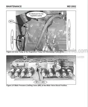
Pressure Check
Test Report
Hydraulic System
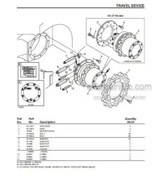
Travel Drive
Tracks
Lubrication Work
Electrical System
Cab
General Maintenance Work
Long-Term Storage
-ENGINE (SN AH00579 AND UP)
Engine Marked 4TNV88-BPNS (SN AH00579 and up): Overview
Fuel System
Preparing For Cylinder Head Removal
Checking And Adjusting Valve Tip Clearance
Removing/Tightening Order For Cylinder Head Bolts
Checking The Injection Nozzles
Checking The Nozzle Jet
Injection Timing
Adjusting Engine Speeds
Compression
Checking The Coolant Thermostat
Checking The Thermal Switch
Oil Pressure Switch
Checking The Coolant Circuit
-ENGINE (SN AD07125 AND BEFORE)
Engine Marked 4TNV88-PNS (SN AD07125 and before): Overview
Fuel System
Checking And Adjusting Valve Tip Clearance
Removing/Tightening Order For Cylinder Head Bolts
Checking The Injection Nozzles
Checking The Nozzle Jet
Injection Timing
Adjusting Engine Speeds
Compression
Checking The Coolant Thermostat
Checking The Thermal Switch
Oil Pressure Switch
Checking The Coolant Circuit
ENGINE TROUBLESHOOTING
-HYDRAULIC SYSTEM
Hydraulic Pump: PVD-2B-41BP-16G5-4713F (SN AH00579 and up) PVD-2B-44BP-16G5-4713F (AD07125 and before)
Main Valve Block
Drive Counterbalancing System
Regeneration – Dipper Arm Section
Bucket Pre-Tension
Flow Rate Adjustment For Auxiliary Hydraulics
Pilot Valves
Valves
Travel Drive
Swivel Unit
Swivel Joint
Breather Filter
Troubleshooting The Hydraulic System
Hydraulics Diagram (Legend)
Options Diagram
Main Valve Block Diagram 5003ZT
Hydraulics Diagram 5003ZT
-ELECTRICAL SYSTEM
Ohm’s Law (Defines Current, Voltage And Resistance Relationship)
Measuring Equipment And Methods
Cable Color Coding
Relays
Electrical Units
Fuse Box In Instrument Panel
Main Fuse Box With Relays
Relays
Socket
Joystick Switch Buttons
Instrument Panel: Overview
Switches Overview (SN AC02893 And Up)
Switches Overview (SN AC02877 And Below)
Alternator
Starter
Wiring Harness Overview
Wiring Diagram (SN AC02890 And Up)
Wiring Diagram Legend (SN AC02889 And Before)
Wiring Diagram (SN AC02889 And Before)
Engine – Chassis Wiring Harness Legend
Engine – Chassis Wiring Harness
Wiring Harness Switches (SN AC02890 And Up)
Wiring Diagram Legend (SN AC02890 And Up)
Wiring Harness Switches Legend (SN AC02889 And Before)
Wiring Harness Switches (SN AC02889 And Before)
Cab Roof Wiring Harness
Armrest Wiring Harness
Boom Working Light Wiring Harness
-OPTIONS
Air Conditioning
Air-Suspension Seat
Counterweight
Long Dipper Arm
Auxiliary Hydraulics Connections
Proportional Controls
Auto-Idle Feature (SN AH00579 And Up)
TORQUE SPECIFICATIONS
What you get
You will receive PDF file with high-quality manual on your email immediately after the payment.


Reviews
There are no reviews yet.