


Factory Service Manual For Mustang Compact Excavator. Manual Contains Illustrations, Instructions, Diagrams For Step By Step Remove And Install, Assembly And Disassembly, Service, Inspection, Repair, Troubleshooting, Tune-Ups.
Format: PDF
Language: English
Pages: 184
Number: 918170 (september 2005)
Bookmarks: Yes
Searchable: Yes
Wiring Diagrams: Yes
Hydraulic Diagrams: Yes
Model
Mustang Compact Excavator
ME8003
Contents
-OPERATION
Important Information About This Service Manual
Abbreviations/Symbols
Identification Of Warnings And Hazards
Designated Use And Exemption From Liability
Serial Plates And Component Numbers
Serial Number Location
Engine Number
Hydraulic Pump Identification Number
Main Valve Block Identification Number
Travel Drive Identification Number
Swivel Unit Identification Number
Machine: Overview
Cab Overview
Cab Legend
Instrument Panel Overview
Instrument Panel Legend
Engine Compartment: Overview
Chassis: Overview
Tilting The Cab
Tilting The Cab Up
Tilting The Cab Down
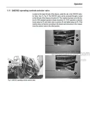
Sae Operating Controls (Standard)
Iso Operating Controls (Selectable)
Boom Slew/Auxiliary Hydraulics Pedal
Dozer Blade
Throttle Lever
Operator’s Seat Adjustments
Ventilation
Windshield
Cab Door Latch Release
Interior Light
Tool Kit And Cab Jack Handle
Cab Heat Control
Recirculated Air Mode
Hydraulics/Swiveling And Boom Rotation Pedal Adjustment
Battery Master Switch
-SPECIFICATIONS
Chassis
Engine
Hydraulic System
Undercarriage/Swivel Unit
Dozer Blade
Electrical System
Sound Levels
Coolant Compound Table
Specific Tightening Torques
General Tightening Torques
Dimensions
Lift Capacities
Lift Capacity Table (With Extended Dipper Arm And Counterweight)
Geometry
-MAINTENANCE
General Information Care And Servicing
Care And Servicing
Maintenance Safety
Fluids And Lubricants
Maintenance Decal Symbols
Maintenance Decal
Maintenance Schedule
General Maintenance
Lubrication
Fuel System
Specific Safety Instructions
Filling The Fuel Tank
Fuel Filter
Fuel Shut-Off Valve, Fuel Prefilter And Water Separator
Purging Air From The Fuel System
Engine Lubrication System
Changing Engine Oil And Filter
Coolant System
Checking Coolant Level
Air Cleaner Service
Dust Valve Functional Check
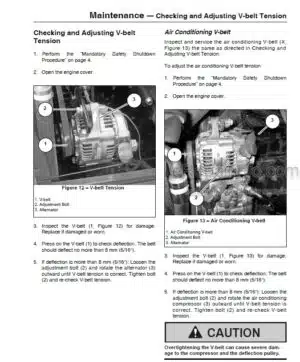
Checking And Adjusting V-Belt Tension
Checking And Adjusting Air Conditioning V-Belt Tension
Pressure Check
Test Report
Hydraulic System
Checking Hydraulic Oil Level
Checking Hydraulic Pressure Lines
Track System
Changing Final Drive Oil
Electrical System
Battery
Using A Booster Battery (Jump-Starting)
Cab Heater Filter
-ENGINE
4TNV98 Engine: Overview
Fuel System
Removing The Cylinder Head Cover
Checking And Adjusting Valve Tip Clearance
Cylinder Head Bolt Tightening Order
Checking The Injection Nozzles
Checking The Nozzle Jet
Injection Timing
Adjusting Engine Rpm
Checking Compression
Checking The Coolant Thermostat
Checking The Thermal Switch
Oil Pressure Switch
Checking The Coolant Circuit
Engine Troubleshooting
-HYDRAULIC SYSTEM
Hydraulic Pump
Main Valve Block
Drive Counterbalancing System
Boom Summation — Raise
Check Valve (Load Retaining Valve)
Dipper Arm Cylinder Summation
Dipper Arm Check Valve (Load Retaining Valve)
Secondary Pressure Limiting Valves For The Auxiliary Hydraulics (Option)
Pilot Valves
Valves
Travel Drive Up To Serial No AC 02793
Travel Drive Auto 2-Speed (Starting Serial No AC 02957)
Swivel Unit
Swivel Joint
Breather Filter
Troubleshooting The Hydraulic System
Hydraulic Diagram (Legend)
Hydraulic Diagram
Main Valve Block Diagram
-ELECTRICAL SYSTEM
Ohm’S Law (Current, Voltage, Resistance); Power
Measuring Equipment, Measuring Methods
Cable Color Coding
Relays
Electrical Units
Fuse Box In Instrument Panel
Main Fuse Box With Relays
Relays
Lubrication Strip Accessory Power Socket
Joystick Tip Switches
Instrument Panel Overview
Switches: Overview
Alternator
Starter
Wiring Diagram Legend
Wiring Diagram
Wiring Harness Legend: Engine—Chassis
Wiring Harness: Engine—Chassis
Wiring Harness Legend: Switches
Wiring Harness: Switches
Wiring Harness: Cab Roof
Wiring Harness: Armrest
Wiring Harness: Boom Working Light
-OPTIONS
Air Conditioning
Counterweight
Extended Dipper Arm
Control Circuit Hydraulic Coupling Connections
3Rd Control Circuit Connections
Auxiliary Hydraulics Connections
What you get
You will receive PDF file with high-quality manual on your email immediately after the payment.


Reviews
There are no reviews yet.