


Factory Service Manual For New Holland AD300 Dump Truck. Manual Contains Illustrations, Instructions, Diagrams For Step By Step Remove And Install, Assembly And Disassembly, Service, Inspection, Repair, Troubleshooting, Tune-Ups.
Format: PDF
Language: English
Pages: 603
Number: 6045615101
Bookmarks: Yes
Wiring Diagrams: Yes
Hydraulic Diagrams: Yes
Model
New Holland Articulated Dump Trucks
AD300
Contents
-MAINTENANCE
General Instructions
Specifications
Tooling
Convers
Safety Instruction
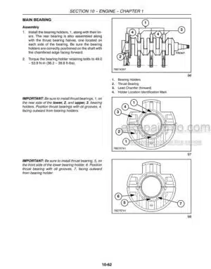
-ENGINE-ENGINE OVERHAUL
External View Of Engine
Engine Lubrication Circuit
Engine Air Intake System
Engine Exhaust System
Engine Fuel Feed System
Engine Cooling System
Coolant Circulation Inside The Engine
Specifications And Data
Diagnostic
Tightening Torques
Special Tools
Engine Removal-Refit
Radiator Removal-Refit
Water-Lubricant Exchanger Removal-Refit On Automatic Transmission
Engine-Periodical Replacement
Engine-Adjustments
Engine – Partial Removals-Refits
-TRANSMISSION-AUTOMATIC TRANSMISSION
Drive Shaft
Gearbox
Pressure Check And Troubleshooting
Transmission Control Valve
-FRONT AXLE-OVERHAUL
Description
First Reduction: Bevel Gear Pair
Second Reduction: Hub And Epicyclic Train
Specifications And Data
Diagnostic
Tightening Torques
Axle
Epicyclical Reduction Gears
Differential
Tools
Epicyclical Reduction Gears
Axle Removal – Refit
Knuckle Hinge Strip Down
Axle-Hinge Strip Down
Specific Maintenance
Checking Axle / Transfer Case Oil Level
Changing Axle / Transfer Case Oil
Epicyclical Reduction Gear
Checking The Dismantled Parts
Checking The Dismantled Parts
Break-Down Drawing Of Self-Locking Differential
Break-Down Drawing Of Pinion
-REAR AXLES-INTERMEDIATE AXLE
Description
First Reduction: Bevel Gear Pair
Second Reduction: Hub And Epicyclic Train
Transfer Unit
Diagnostic
Tightening Torques
Axle
Epicyclical Reduction Gears
Differential
Tools
Epicyclical Reduction Gears
Differential
Axle Removal – Refit
Axle-Rocker Arm Support – Parking Brake Strip Down
Specific Maintenance
Checking Axle / Transfer Case Oil Level
Changing Axle / Transfer Case Oil
Epicyclical Reduction Gear
Checking The Dismantled Parts
Differential And Splitter
Checking The Dismantled Parts
Lockable Splitter
Self-Locking Differential
Location Of Spacers / Adjustment Ring Nuts And Relative Bearings
Finding The Thickness Of Spacer S1 For Pinion Axial Position
Pinion Bearing Axial Pre-Load: Nil
Shape And Position Of Contact Area
-REAR AXLE
Description
First Reduction: Bevel Gear Pair
Second Reduction: Hub And Epicyclic Train
Specifications And Data
Axle
Epicyclical Reduction Gears
Epicyclical Reduction Gears
Axle Removal – Refit
Axle – Knuckle Hinge Strip Down
Specific Maintenance
Checking Axle / Transfer Case Oil Level
Changing Axle / Transfer Case Oil
Epicyclical Reduction Gear
Checking The Dismantled Parts
Checking The Dismantled Parts
Break-Down Drawing Of Self-Locking Differential
Break-Down Drawing Of Pinion
-BRAKES-BRAKE OVERHAUL
Specifications
Torque Specifications
Special Tools
Description
Troubleshooting
Overhaul
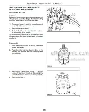
-HYDRAULIC SYSTEM-HYDRAYLIC CIRCUITS AND COMPONENTS
Hydraulic System
Main Hydraulic System
Front Layout
Steering – Tipping (Version Without Retarder)
Steering – Tipping (Version With Retarder)
Main Hydraulic System
Rear Layout
Steering Tipping
Description Of Components
Main Hydraulic System
General Lay-Out
Brakes
Main Hydraulic Pump
Brake Hydraulic Pump
Steering Emergency Electro-Pump
Tipper Cylinders
Tipper Control Distributor
Power Steering
Counterbalancing Valve
Flow Amplifier
Hydraulic System Diagram
Maintenance
Changing Hydraulic Oil
Replacing Pressurised Oil Filter (Pump Outlet)
Replacing Inner Hydraulic Oil Filter (Intake)
Changing Hydraulic Brake Oil Filter
Checking Fitting And Pipe Tightness
Bleeding The Hydraulic System
Checks And Verify
Hydraulic Pressure Test Point
Main Pressure Test Point
Steering Pressure Test Point
6WD Pressure Test Point
Main Pump Removal – Refitting
Brake Pump Removal – Refitting
Steering Valve Removal – Refitting
Rate Of Flow Amplifier Removal – Refitting
Tilt Valve Removal – Refitting
Steering Cylinder Removal – Refitting
Tilt Cylinder Removal – Refitting
-STEERING SYSTEM-Steering Circuit
Description
Troubleshooting
Steering Valve
-WHEELS-TIRES AND WHEELS
Specifications
Torque Specifications
Troubleshooting
Description
Replacing A Complete Wheel
Tire And Wheel Checks
-SUSPENSION-SUSPENSION OVERHAUL
Specifications
Torque Specifications
Special Tools
Description
Troubleshooting
Suspension Cylinder
-ELECTRICAL SYSTEM-WIRING DIAGRAM
Technical Data
International System Units (S.L.)
Main Elements – Resistivity And Temperature Coefficient
Resistor Colour Codes
General Instructions
General Precautions
General Precautions For Electronic Components
The Concept Of Earth And Electromagnetic Compatibility
Practical Hints
Cable Colour Codes
Identification Of The Electric Function By The Cable Colour Code
Control Units Location
Transmission Control Unit
Interconnection Control Unit
Fuse
Teleruptors
Layout Electrical System
-CAB AND CHASSIS
Cab And Chassis
Body
What you get
You will receive PDF file with high-quality manual on your email immediately after the payment.


Reviews
There are no reviews yet.