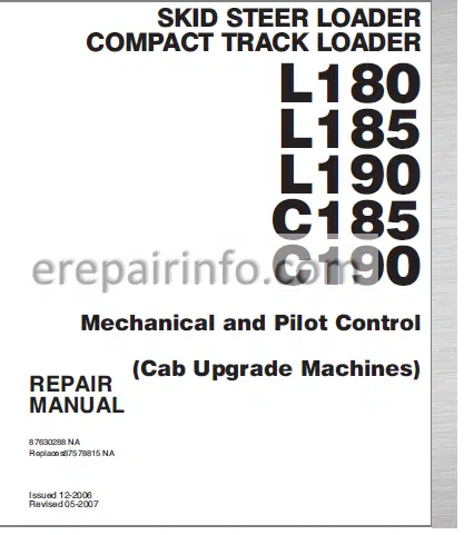
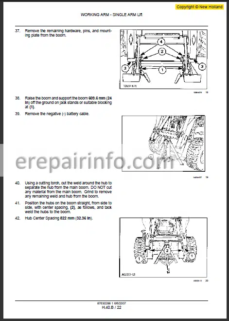
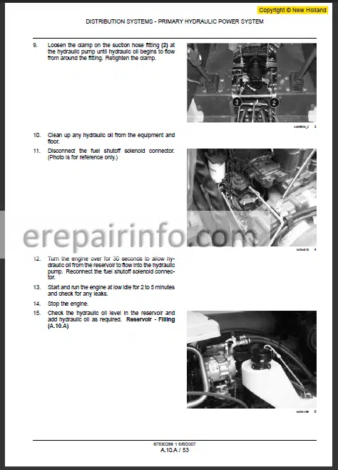
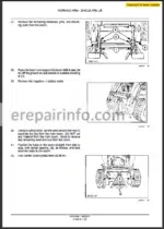
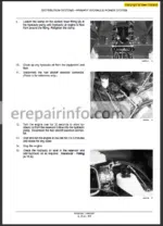
Repair Manual For New Holland L180 L185 L190 C185 C190. Illustrations, instructions, diagrams for step by step remove and install, assembly and disassembly, service, inspection, repair, troubleshooting, tune-up.
Format: PDF
Language: English
Pages: 1068
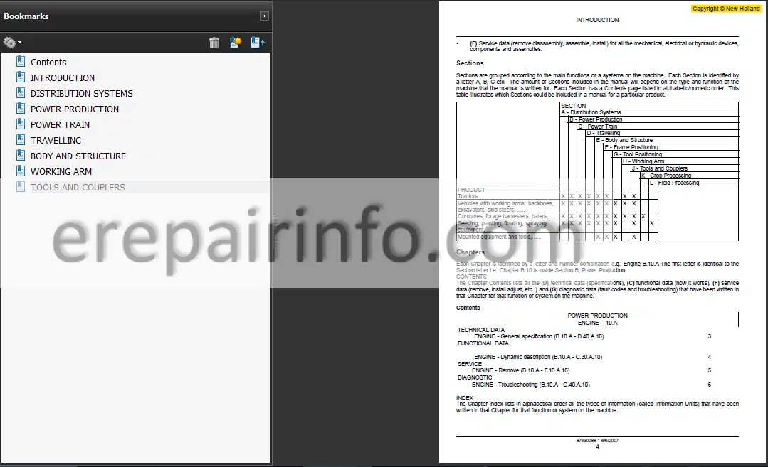
Bookmarks: Yes
Searchable: Yes
Number: 87630288
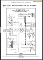
Wiring Diagrams: Yes
Hydraulic Diagrams: Yes
Model
New Holland L180, L185, L190, C185, C190
Cab upgrade Machines
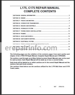
Contents
- – Introduction
Basic Instructions
Torque
Conversion Factors - – Distribution Systems
Primary Hydraulic Power System
Secondary Hydraulic Power System
Highflow
Hydraulic Power System
Electrical Power System
Lighting System
Relief Valve
Hydraulic Pump
Filter Bypass
Functional Data
Primary Hydraulic Power System
Hydraulic Schematic Frame
Hydraulic Pump
Charge Pump
Reservoir
Filter
Oil Cooler
Sensing System
Temperature Sensor Testing
Filter Restriction Sensor Testing
Secondary Hydraulic Power System
Hydraulic Power System
Control Valve
Hydraulic Power System Cleaning
Hydraulic Power System Decontaminating
Hydraulic Power System Exploded
Hydraulic Power System General
Hydraulic Power System General
Alternator
Torque
Service Limits
Battery
Alternator
Sectional View
Connector
Component Diagram
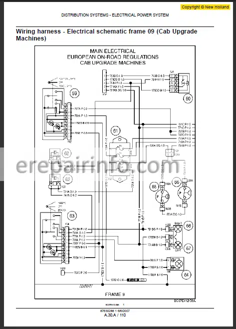
Wiring Harness
Electrical Schematic Frame
Auxiliary Fuse And Relay Box Testing
Auxiliary Fuse And Relay Box Left Power Switch Testing
Auxiliary Fuse And Relay Box Relay Testing
Auxiliary Fuse And Relay Box Right Power Switch Testing
Auxiliary Power Connection
Battery
Connector Component
Diagram
Fuse And Relay Box
Wiring Harness Electrical Schematic Frame
Marker Light
Indicator Lamp Testing
Switch Testing
Turn/Hazard Light
Diode Testing
Turn Switch Testing
Beacon
Switch Testing
Testing
Rear Work Light
Electrical Light Testing
Front Work Light
Electrical Light Testing
Brake Light
Switch Testing
Road Light
Testing - – Power Production
Engine
Fuel And Injection System
Air Intake System
Engine Coolant System
Lubrication System
Starting System
Fuel Tank
Throttle Command
Mechanical Throttle Tension
Level Sensor Testing
Sensing System
Air Cleaner Restriction
Engine Coolant System
Radiator
Drain Fluid
Sensing System
Coolant Temperature
Lubrication System
Engine Starter
Start Control - – Power Train
Power Coupling Fixed Coupling
Transmission Hydrostatic
Drive Plate
Pump Drive
Pump
Relief Valve
Pressure Test
Travel Adjust
Bleed (Machines Equipped With Pilot Controls) (Procedure To Bleed Air From The Pilot
Control Hydraulic System)
Right Hand Pump
Left Hand Pump - – Travelling
Front Axle
Rear Axle
Steering Steering Clutch
Parking Brake Hydraulic
Wheels And Tracks Tracks
Wheels And Tracks Wheels
Final Drive
Front Axle
Rear Axle
Steering Clutch
Parking Brake Hydraulic
Button Testing
Sensing System
Pressure Sensor Testing
Electrical Control
Electrical Control Solenoid Testing
Sensing System Pressure
Wheels And Tracks Tracks
Drive Sprocket
Roller
Idler Wheel
Frame
Drive Sprocket
Rubber Track
Tension Adjust
Track Tensioning Mechanism
Idler Wheel
Drive Chain
Housing
Wheel Hub Housing - – Body And Structure
User Controls And Seat
User Platform
Environment Control Heating System
Environment Control Airconditioning System
Safety Security Accessories Safety
Console
Component Diagram
Instrument Panel
Component Diagram
Static Description
Seat
Rops
Tilt
Wiper System
Wiper System Motor Testing
Wiper System Switch
Heat Command
Fan Speed Switch Remove
Fan Speed Switch Install
Heater
Louver
Ventilation System
Air Filter
Diagnostic
Heat Command
Fan Speed Switch Testing
Ventilation System
Evaporator
Receiver/Drier
Environment Control
Hydraulic Lockout
Diode Testing
Relay Testing
Electrovalve Testing
Back Up Alarm
Testing
Left Switch Testing
Right Switch Testing
Audible Alert
Switch Testing
Horn Testing
Operator Presence System
Audible Alert Horn Testing
Audible Alert Switch Testing
Back Up Alarm Testing
Back Up Alarm Left Switch Testing
Back Up Alarm Right Switch Testing
Hydraulic Lockout
Diode Testing
Hydraulic Lockout
Electrovalve Testing
Hydraulic Lockout
Relay Testing
Operator Presence System (Ops) Seat Switch Testing - – Working Arm
Single Arm Lift
Single Arm Tool Attachment Tilt
Control Valve
Relief Valve
Single Arm Tool Attachment Tilt
Lever
Single Arm Tool Attachment Tilt - – Tools And Couplers
Carrying Unarticulated Tools
Coupling Hydraulic Coupling
Coupling Mechanical Coupling
Bucket
Cutting Edge
Hydraulic Coupling
Connector
What you get
You will receive PDF file with high-quality manual on your email immediately after the payment.

Anonymous (verified owner) –
Been looking for this data hard to find some of these things