Repair Manual For New Holland LM415A, LM425A, LM435A, LM445A Telehandlers.
Manual includes step by step instructions, illustrations, diagrams. Remove, Install, disassemble, assemble, repair procedures, troubleshooting, and other servicing procedures. This repair manual provides the technical information needed to properly service the New Holland Telehandlers.
Format: PDF
Language: English
Pages:944
Bookmarks: Yes
Searchable: Yes
Number: 87751937
Wiring Diagrams: Yes
Hydraulic Diagrams: Yes
Model
New Holland LM415A, LM425A, LM435A, LM445A
Contents
- – General
General Instructions
Important Notice
Shimming
Rotating Shaft Seals
‘O’ Rings
Sealers
Bearings
Spring Pins
Notes For Spare Parts
Notes For Equipment
Notices
How to Move the Vehicle with the Battery Removed
Safety Rules
To Prevent Accidents
Safety Rules
Generalities
Start Up
Engine
Electrical Systems
Hydraulic Systems
Wheels and Tires
Removal and Installation
Product Identification
Vehicle Product Identification Number
Vehicle Identification Plate
Engine Identification
Front Axle Identification
Transmission Identification x Power Shuttle
Transmission Identification x Power Shift
Rear Axle Identification
Identification Plates in the Cab
Important Ecological Considerations
Precautions
Service Techniques
General
Hoses and Tubes
‘O’ Ring Flat Face Seal Fittings
Sealer Specifications - – Engine
Specifications
Of Bosch Injection Pump
Calibration Test Conditions
Assembly
Calibration Test Conditions
Tightening Torques
Troubleshooting
Coding Of Source EnginesFGeCFGeG
Engine
Checks, Measurements And Repairs
Crankcase
Crankshaft
Connecting Rods
Pistons
Valves
Camshaft
Cylinder Head
Oil Filter - – Transmission
Description And Operation
Transmission Control
Transmission Disconnect Switches
Torque Converter
Gear Train
Gear Shift Mechanism
Co Axial Drive Vehicle Hydraulic Pump
Transmission Hydraulic Pump Oil Supply
Oil Flow
Transmission Oil Supply Ports
Transmission Oil Flow Through Solenoid Valve
Oil Flow Solenoid Control Valve Operation (Forward Drive Only Shown)
Transmission Hydraulic Valves And Pressure Test Points
Transmission Power Flows
Fault Finding
Stall Procedure
Stall Speed
Overhaul
Forward / Reverse Control Solenoid Valve
Solenoid Valve
Resistance Checking Of Coils
Oil Pump
Transmission Overview
Transmission Overhaul - – Drive Lines
Tightening Torque
Description of Operation
Drive Line Power Flow
Drive Shaft Removal
Rear Lower Driveshaft
Upper Driveshaft
Front Lower Driveshaft
Driveshaft Installation
Center Bearing
Driveshaft Components - – Front Axle
Sealants
Torque Specification
Description Of Operation
Front Axle
Housing
Transfer Gear Box
Hubs
Component Overhaul
Axle In Place
Axle Removed
Axle Removal Procedure
Overhaul
Planetary Reduction Assembly And Wheel Hubs
Disassembly
Steering Rod End Ball Joint Removal
Swivel Pin Removal
Swivel Housing Removal
Handbrake Lock
Shaft Retaining Lock Nuts
Axle Shaft Removal
Swivel Hub Seal Removal
Swivel Pin Bearing Removal
Removal Of Lower Swivel Pin Bearing Cone
Removal Of Shaft Bearing And Seal Housing
Reduction Hub, Swivel Housing And Axle Shaft Reassemble
Hub Oil Seal Installation
Swivel Housing Seal Installation
Swivel Pin Bearing Cone Installation
Lower Swivel Pin Bearing Cone Installation
Steering Cylinder Removal
Steering Cylinder Disassembly
Transfer Gearbox Disassembly
Axle Trumpet Housing Removal
Differential Assembly Removal
Differential Disassembly
Pinion
Bearing Preload
Differential Preload
Crown Wheel To Pinion Backlash - – Rear Axle
Torque Specification
Description of Operation
Load Sensor
Component Overhaul
Axle In Place
Axle Removed
Axle Removal Procedure
Overhaul
Pivot Bushes
Load Sensor Installation - – Brakes
Brake Master Cylinder
Brakes Released
Brakes Applying
Brakes Applied
Fault Finding and Pressure Testing
Brake Bleeding Procedure
Machine Preparation
Servo Circuit Pressure Testing
Overhaul
Brake Master Cylinder
Removal
Installation
Master Cylinder Overhaul
Assembly
Ports
Push Rod Components
Servo Housing
Brake Piston
Return Spring & Feed Valve Assembly
Fluid Feed Valve Replacement
Front Axle Brake Disassembly
Brake Piston Assembly
Rear Axle Brake Disassembly
Brake Piston Assembly
Parking Brake Operation
Handbrake Adjustment
Handbrake Lever
Front Axle
Adjustment Procedure - – Hydraulic Systems
Introduction
Gear Type Hydraulic Pump
Brake Circuit Accumulator And Pressure Reducing Valve
Hydraulic Control Valves
Telescopic Loader Controls
Hydraulic Cylinders
Counterbalance Valves
Hydraulic Circuit
Basic Circuit Operation
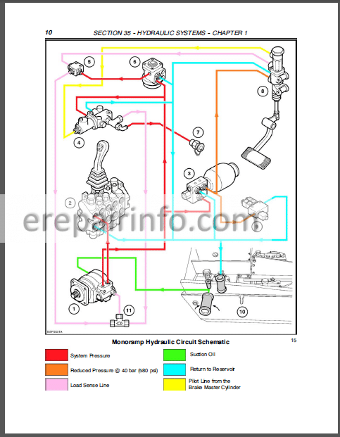
Monoramp Hydraulic Circuit Schematic
Component Operation
Hydraulic Pump
Flow Divider Valve
Pressure Reducing Valve And Accumulator
Pressure Reducing Valve Operation
Hydraulic Control Valves
Control Valve Oil Flow
Circuit Relief Valves
Direct Acting System Relief Valve
Circuit Relief Valves
Monoramp Control System
Control Buttons Released
Control Button Depressed
Fault Finding And Pressure Testing
Fault Finding
Flow And Pressure Testing
Preparation
Flow Testing (Using Auxiliary Test Hydraulic Ports)
Pump Cavitation Test
Performance Test
Alternative Method
Pressure Testing (Using Auxiliary Test Hydraulic Ports)
Using Auxiliary Test Hydraulic Ports
System Pressure Test
Telescopic Circuit Relief Valve Pressure Test
Tilt Cylinder Pressure TeSt
Piston End Circuit Relief Valve
Lift Cylinder Circuit Relief Valves Pressure Test
Pressure Testing (Using Control Valve Test Port)
Preparation
System Pressure Test
Telescopic Circuit Relief Valve Pressure Test
Tilt Cylinder Pressure Test
Piston End Circuit Relief Valve
Boom Lift Cylinder Circuit Relief Valve Pressure Test
Adjustment Of Circuit Relief Valves
Servo Hydraulic Circuit Pressure Test
Component Overhaul
Hydraulic Control Valve
Accumulator And Pressure Reducing Valve
Solenoid Control Valves - – Chassis
Vehicle Chassis Type
Overhaul
Engine, Torque Convertor and Transmission
Front Axle and Rear Axle
Hydraulic Brake
Hydraulic Loader Valve PackMechanical & Monoramp Controls
Hydraulic Telescopic Boom Controls
Frame Attachments
Hydraulic Steering Control
Loader
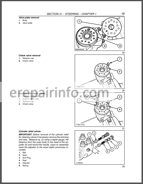
Chassis / Cab - – Steering
Component Operation
Hydraulic Pump
Flow Divider
Pressure Testing
Preparation
Pressure Test
Steering Motor Shock Relief Valves
Steering Control Valve Removal
Overhaul
Steering Motor Inspection
Component Inspection
Replace the End Cover
Pressure Testing - – Cab Environment
Sealants
Torque
Description And Operation
Cab Climate Controls
Heater Blower Control
Heater Temperature Control
Air Flow Vents
Windshield Demisting
Heater Radiator
Cab Air Filter
Draining The System
Heater Radiator
Blower Motor
Heater Control Valve - – Electrical System
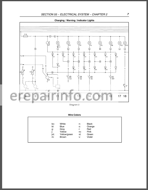
Electrical System And Fuses
Fuses And Relays
Powershuttle Fuses & Relays
Powersoft Fuses & Relays
Controls And Instruments
Mechanical
Mono Ramp
Flow Sharing
Cab Instruments And Controls
Lamps And Operating Lever For Alignment Of The Wheels
Lamp Indicator Panel
Alignment Of The Wheels
Instrument Console
Engine Coolant Temperature Warning Gauge (With Warning Buzzer)
Tachometer And Hour Meter
Fuel Level Gauge
Warning Lights
Load Status Indicator Panel
Led’S (Visual Alarm)
Sound Alarm Switch
Test Switch
Hydraulic Load Automatic Cut Off (Where Fitted)
Lifting From Ground Level
Lowering From A High Position
Hydraulic Load Cut Off (In A Worsening Situation)
MultiFunction Lever
Switches
Interior Light
Bulb Replacement
Work Lamp Bulb Replacement
Headlight And Indicator Bulb Replacement
Loader Mounted Work Lights
Interior Lamp Bulb Replacement
Rear Work Lamps
Rear, Stop And Indicator
Reversing Lamps
Rocker Switch Bulb Replacement
Protecting The Electrical Systems
Charging Or Welding
Starting The Machine With Jump Leads
Temporary Wiring Harness Repair
Troubleshooting - – Loader
Description Of Operation
Telescopic Loader Controls
Mechanical Controls
Mono Ramp System Controls
Flow Sharing System Controls
Loader Boom Wear Pads
Removing The Wear Pads At The Base Of The Loader Boom
Tilt Cylinder And Auxiliary Hoses
Replacement
Section Boom
Tilt Cylinder
Telescopic Boom Cylinder
Telescopic Boom
Loader Boom Assembly - – Cab
Hand And Foot Operating Controls
Mechanical
Mono Ramp
Flow Sharing
Description And Operation
Cab Disassembly
Inside The Cab
Underside Of The Cab
Cab Heater Hoses
Air Conditioning (Where Fitted)
Electrical/Harness Connections
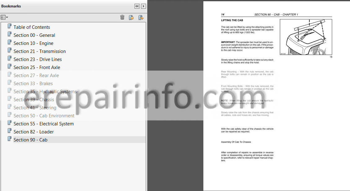
Lifting The Cab
Overhaul
Cab Internal Parts
Seats
Steering Column
Instrument Panel
Inner Roof Panel
Windshield Wipers
Roof Panel
Cab Glass Replacement (Bonded)
Glass Intact
Glass Broken
New Glass
Existing Glass
What you get
You will receive PDF file with high-quality manual on your email immediately after the payment.


Reviews
There are no reviews yet.