


Factory Service Manual For New Holland Telehandler. Manual Contains Illustrations, Instructions, Diagrams For Step By Step Remove And Install, Assembly And Disassembly, Service, Inspection, Repair, Troubleshooting, Tune-Ups.
Format: PDF
Language: English
Pages: 641
Number: 84571197A
Bookmarks: Yes
Searchable: Yes
Wiring Diagrams: Yes
Hydraulic Diagrams: Yes
Model
New Holland Telehandler
LM625
Contents
– GENERAL
General Instructions
Safety Rules
Product Identification
Environmental Considerations
Maintenance Techniques
Specific Sealing Compounds
Minimum Tightening Valves For Threaded Fasteners
Minimum Tightening Torques For Fasteners
Load Tables
Table Of Lubricating Oils
-ENGINE
Main Engine Specifications
Engine Model Views
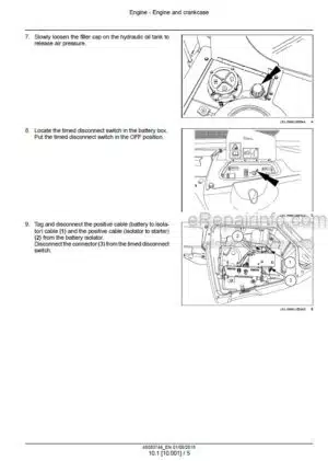
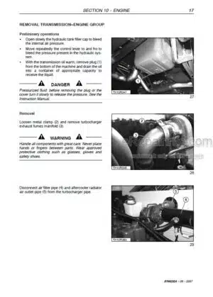
Removal And Installation Of Engine And Radiator
Removal
Installation
Filing The Engine Cooling System
Bleeding Air From The System
Important Warnings
-TRANSMISSION
Variable Displacement Motor
Exchanging Seals
Exchanging The Controller
Sealing The Cover
Checking
Checking Beginn Of Regulation Control Ep
Checking Beginn Of Regulation Control Hd
Checking Beginn Of Regulation Control Ha
Checking Beginn Of Regulation Control Da1/4, Da2, 3, 4, 5, 6
Variable Displacement Pump
-FRONT AXLE
Wheel Toe-In Check
Component Overhaul
Front Axle Removal Procedure
Planetary Reduction 1:6 And The Steering Case
Steering Cylinder
Differential: Normal Preloaded Differential Unit
Flanged Reduction Gear 603 Type: Integral 603 Input Gear
Bevel Pinion: Version Normal Flange And Nut Revolution Counter Version
Ring And Pinion Adjusting: Step For Preloaded Differential
Swinging Support
Planetary Reduction: 1:4,23
Differential: Preloaded Limited Slip Differential Unit
Differential: With Block To Spheres 100%
Differential: Normal Differential
Differential: Limited Slip Differential Unit (45%)
Update Limited Slip Differential
Update Differential With Service, Negative And 100% Lock Brake
Bevel Pinion: Flanged To Reductor Gear 603
Ring And Pinion Adjusting: Version Pinion Cover And Single Arm
Ring And Pinion Adjusting: Version Pinion Integral And Double Arm
Drive Shaft Removal
Special Tools
-REAR AXLE
Drive Shaft Removal
Reattachment
Rear Axle Removal Procedure
Overhaul
Installation
-BRAKES
Disassembly The Incoming Disc Brake
Assembly The Incoming Disc Brake
Disassembly Brake: Service Brake And Mechanic Parking Brake
Assembly Brake: Service Brake And Mechanic Parking Brake
Disassembly Brake: Service Brake And Differential Hydraulic Lock 100%
Assembly Brake: Service Brake And Differential Hydraulic Lock 100%
Disassembly Brake: Service Brake, Negative Brake, 100% Locked
Assembly Brake: Service Brake, Negative Brake, 100% Locked
Disassembly Brake: Negative Brake 4 Cup Springs
Assembly Brake: Negative Brake 4 Cup Springs
– HYDRAULIC SYSTEM
Hydraulic System Circuit
Hydraulic Control Valve
Cylinders
Lifting Cylinder
Boom Lifting Phases
Boom Descent Phases
Lifting Cylinders Dismounting Instructions
Boom Overhaul
Replacement Of Internal Boom Tube
Replacement Of Carrier Chain
Tilt Cylinder Replacement
Extension Cylinder Replacement
Boom Extension Replacement
-ELECTRICAL SYSTEM
Electrical System – General
Circuit Diagrams
What you get
You will receive PDF file with high-quality manual on your email immediately after the payment.


Reviews
There are no reviews yet.