


Repair Manual For New Holland TC31DA TC34DA Tractors. Illustrations, instructions, diagrams for step by step remove and install, assembly and disassembly, service, inspection, repair, troubleshooting, tune-up.
Format: PDF
Language: English
Pages: 814
Bookmarks: Yes
Searchable: Yes
Number: 87531026
Wiring Diagrams: Yes
Hydraulic Diagrams: Yes
Model
New Holland TC31DA, TC34DA
Contents
- – General Information
Precautionary Statements
Personal Safety
Machine Safety
Information
Safety
Precautionary Statements
The Tractor
Servicing The Tractor
Operating The Tractor
Driving The Tractor
Operating The Pto
Diesel Fuel
Safety Frame (Rops)
Decals
Safety Decals
Instruction Decals
Ecology And The Environment
Helpful Hints
International Symbols
Specifications
General Dimensions
Minimum Hardware Tightening Torques
Lubrication And Maintenance
Lubrication
Liquid Ballast (Optional)
Tire Pressure
Rear Tire Liquid - – Engine
Specifications
Engine Bolt Torque Specifications
Engine Fuel System Bolt Torque Specifications
Metric Bolt Torque Specifications
Compression Test And Tools
Description Of Operation General Information
Cylinder Head And Valve Train Components
Cylinder Block Assembly
Preparation
Fuel Injector And Glow Plug
Oil Pressure Switch
Temperature Sending Switch And Alternator
Fan, Water Pump And External Oil Tube
Head Cover
Rocker Arm Shaft And Support Bracket
Cylinder Head
Valve Tappet
Fuel Shutoff Solenoid
Timing Gear Cover
Timing Gears And Camshaft
Sump
Oil Suction Pipe And Strainer
Connecting Rods, Bearings, Pistons And Rings
Flywheel
Backplate And Oil Seal
Front Crankshaft Gear
Crankshaft And Main Bearings
Cylinder Head
Inspection And Repair
Valve Seats
Valves
Valve Guides
Valve Springs
Rocker Arms
Push Rods
Cylinder Block
Pistons
Piston Rings
Connecting Rods
Connecting Rod Bearing Oil Clearance Check
Pistons, Rings And Connecting Rod
Main Bearing And Thrust Washer
Crankshaft
Crankshaft Bearing (Bushing)
Replacement
Crankshaft Front Gear, Main Bearings And Thrust Washers
Port Block
Timing Gear
Flywheel
Timing Gear Housing
Front Oil Seal And Steering Pump Seal
Crankshaft And Bearing Holder
Rear Oil Seal And Backplate
Flywheel
Pistons And Connecting Rods
Oil Suction Pipe And Suction Strainer
Oil Sump
Camshaft And Camshaft Gear
Idler Gear, Oil Pump And Injection Timing
Timing Gear Cover
Crankshaft Pulley
Fuel Injection Pump
Power Steering Pump
Head Gasket Selection
Cylinder Head
Valve Clearance Adjustment
Head Cover
Water Pump And Cooling Fan
External Oil Tube
Glow Plug And Connector
Fuel Injector
Fuel Piping
Alternator And Temperature Sender Switch
Installation
Exhaust Manifold
Description Of Operation – Engine Lubrication System
Oil Filter
Engine Oil Pressure Check
Oil Pressure Relief Valve
Oil Consumption
Description Of Operation Cooling System
Coolant
Radiator Cap
Thermostat
Water Pump
Cooling Fan
Radiator
Water Pump
Thermostat - – Clutch
Description Of Operation- Single Clutch
Hst Transmission
FreePlay
Single Clutch
Description Of Operation – Double Clutch
Gear Transmission
FreePlay
Pto Clutch
Double Clutch
Double Clutch Adjustments
Servicing ClutchRelated Components
Clutch Pilot Bearing
Clutch Dimensions
Clutch Release Bearing
Clutch Linkage Components
Clutch Cross Shaft Bushings
Clutch Pedal Bushings - – Gear Transmission
Powerflow
Initial Power Flow
Fwd Power Flow
Transmission Preparation
Separating Clutch Housing/Transmission
Separating Transmission/Differential
Clutch Housing
Shift Rails
Main Shaft And Gears
Pto Countershaft And Gears
Countershaft And Gears
Reverse Idler Shaft And Gear
Fwd Shift Rail
Fwd Driveshaft And Gear
Rear Main Shaft And Gears
Range Gear Shift Rail, Arm And Fork
Drive Pinion And Gears
Preparation
Drive Pinion And Gears
Range Gear Shift Rail, Arm And Fork
Rear Main Shaft And Gears
Fwd Driveshaft And Gear
Fwd Shift Rail
Reverse Idler Shaft And Gear
Countershaft And Gears
Pto Countershaft And Gears
Main Shaft And Gears
Shift Rails
Clutch Housing
Transmission Differential
Clutch Housing/Transmission
Clutch Housing/Engine
Main Shift Lever - – Fwd Axle
Front To Rear Axle Ratio
Description Of Operation – Supersteer, Front Axle And Sensitrack Automatic Position
Full Time Front Wheel Drive (Locked Down)
Supersteer Front Axle
Sensitrack
Cable Adjustment
Supersteer Axle
Supersteer Axle Components
Reduction Gear- Drop Box
Reduction Gear Box Assembly
Seal Installation
Front Axle And Differential
Drive Pinion
Front Axle
Front Axle And Differential
Differential Gear
Axle And Differential
Ring GearToPinion
Backlash Check And Adjustment
Supersteer Axle
Crankshaft Pulley
Steering Stops - – Differential, Rear Axle
Ring Gear And Pinion Gear Pattern Specification And Adjustment
Bolt Torque Specifications
Description Of Operation – Differential Assembly
Differential Lock
Drive Pinion
Differential
Description Of Operation – Rear Axle
Rear Axle - – Hydrostatic Transmission
Hydrostatic Transmission
Bolt Torques
Minimum Hardware Tightening Torques
Special Tools
Troubleshooting
Description Of Operation- Hydrostatic Transmission
Hydrostatic Transmission
Variable Displacement Pump
Fixed Displacement Motor
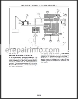
Fluid Flow
Neutral Position
Forward Position
Reverse Position
Hst Charge Circuit
Hydrostatic Transmission
Separating The Tractor Between The Engine And Clutch Housing
Attaching The Tractor At Engine And Clutch Housing
Separating The Tractor Between The Hydrostatic Transmission And The Rear Axle Center Housing
Hydrostatic Unit
Hydrostatic Gearbox
Hydrostatic Unit And Gearbox
Hydrostatic Pump
Hydrostatic Motor
Hydrostatic Motor Shaft
Charge Pump
Swash Plate
Hydrostatic Pump
Hst Piston Pump Cylinder Block
Hst Motor Cylinder Block
Port Block Neutral And Feed Valves
Neutral Valve
Charge Pump Relief Valve
High Pressure Relief Valve
Hydrostatic Pump And Port Block
Motor And Port Block
Hst Cooler Check Valve
Pressure Tests
High Pressure Relief Valve
High Pressure Relief Valve Access (Alternate Method)
Charge Pump Relief Valve
Description Of Operation- Gearbox
Hydrostatic Transmission Gearbox
Hst
Gearbox Power Flow
Gearbox
Gearbox
Gearbox Case
Pto Input Shaft
Transmission Input Shaft
Fwd Shift Rod
Fwd Drive Shaft
Rear Main Shaft
Range Gear Shifter Rod
Drive Pinion Shaft
Pto Countershaft
Gearbox Components
Pto Countershaft
Range Gear Shifter Rod
Rear Main Shaft
Fwd Main Shaft
Transmission Input Shaft
Pto Input Shaft
Gearbox
Rear Pto Link
MidPto Link
Range Gear Link
Hst Neutral Position
Treadle Forward Stop
Treadle Rear Stop Adjustment
Cruise Control Adjustment
Hst Neutralizer - – Power Take Off Systems
Description Of Operation- Live Power TakeOff
Live Power TakeOff
Power TakeOff Drive- Hydrostatic Transmission
Overhaul- Power TakeOff
Power Take Off
Output Shaft
Rear Countershaft
Front Countershaft
Shifter
Front Countershaft
Rear Countershaft
Center Countershaft
Output Shaft
Description Of Operation- MidMount Power TakeOff
MidMount Power TakeOff
Overhaul- MidMount Power TakeOff
Countershaft
Shifter Arm
Gear Box
Gear Shifter
Output Shaft
Gear Box
Output Shaft
Gear Shifter
Shifter Arm
Countershaft - – Brakes
Description Of Operation
Brakes
Parking Brake
Brake Adjustment - – Hydraulic System
Description Of Operation- Hydraulic System
Hydraulic Fluid Filter
Combination System Relief – Diverter Valve Manifold
Control Valve (Hpl)
Fluid Flow
Flow Priority
Neutral Position
Raising Position
Lowering Position
Bypass Spool
Flow Control Valve
Linkage Operation- Single Lever- Position Control
Position Control Operation
Neutral Position To Raise Position
Raise Position To Neutral Position
Neutral Position To Lowering Position
Troubleshooting
Pressure Testing
Main System Relief Valve
Inlet Restriction Test
Pump Efficiency Test
Lift Cylinder
Lift Cylinder
Flow Control Valve
Hydraulic Control Valve (Hpl)
Combination System Relief Valve And Diverter Valve
Hpl Linkage
Adjustment Procedure
Control Lever
Description Of Operation – Hydraulic Pump And Filter
Hydraulic Pump And Filter
Hydraulic Pump
Description Of Operation – Remote Valves
Remote Valves
Rear (Single Spool) Remote Valve
Front (Double Spool) Remote Valve
Fluid Flow
Neutral Position- Rear (Single Spool) Remote System
Remote Cylinder Extending- Rear (Single Spool) Remote System
Remote Cylinder Retracting- Rear (Single Spool) Remote System
Front (Double Spool) Remote Control System Bucket Control- Neutral
And Lift Control- Neutral
Bucket Control- Dumping And Lift Control- Neutral- Front (Double Spool)
Remote Control System
Bucket Control- Dumping Regen And Lift Control- Neutral Front (Double Spool) Remote Control System
Bucket Control Rollback And Lift Control Neutral Front (Double Spool)Remote Control System
Bucket Control- Neutral And Lift Control- Raising- Front (Double Spool)
Remote Control System
Bucket Control- Neutral And Lift Control- Lowering- Front (Double Spool)
Remote Control System
Bucket Control- Neutral And Lift Control- Float- Front (Double Spool) Remote Control System
Rear (Single Spool) Remote Valve
Front (Double Spool) Remote Control Valve - – Steering Systems
Description Of Operation- Power Steering System
Description Of Operation- Supersteer
PowerSteering Control Motor
Power Steering Pump
Fwd Power Steering Cylinder
Fwd Power Steering Operation
Fwd Manual Operation
Supersteer Power Steering Operation
Supersteer Manual Operation
Pressure Testing
Pump, Steering Motor And Relief Valve
Steering Cylinder
Steering Stops
Power Steering Control Motor
Fwd Steering Cylinder
Supersteer Steering Cylinder
Power Steering Pump
Inspection And Repair
Power Steering Tubes
Steering Column
Removal And Disassembly
Assembly And Installation
Adjustable Steering Column - – Wheels And Tires
Fwd Tread Setting
Front Wheel Settings
Rear Wheel Settings
Rear Axle Tread Setting
Tractor Weighting
Weighting For Stability
Weighting Limitations
Rear Wheel Weight Installation
Liquid Ballast
Tire Pressure
Rear Tire Liquid
Wheel Nut Torque Specification - – Electrical System
Description Of Electrical System
Component Location And Function
Wiring Harnesses
Grounds
Battery And Fuses
Battery
Checking The Battery Electrolyte Level
Fuse Block
Main Fuse
Electrical System Components – Description And Testing
Key Switch
Testing
Light Switch
Terminal Identification
Testing
Hazard Light Switch
Turn Signal Switch
Transmission Range Safety Switch
Rear Pto Safety Switch
Testing
Mid Pto Safety Switch
Testing
Park Brake Safety Switch
Cruise Control Brake Release Switch
Seat Safety Switch
Diodes
Testing Micro Relays
Hazard Flasher/Turn Signal Control Module
Operator Safety Module
Park Brake Safety Alarm (Buzzer)
Glow Plug Indicator Light Controller
Cruise Control Magnet
Description
Cruise Control Switch
Glow Plugs
Engine Sensors
Engine Oil Pressure Sender
Engine Coolant Temperature Sender
Fuel Level Sender
Fuel Shutoff Solenoid
Lighting
Head Lamp
Taillight
Flasher Warning Light
Rear Worklight
Auxiliary Electrical Power Socket - – Platform
Platform
Hood
Rear Hood Panels
Dash Console
Seat
Rops
Fenders
Deck
Pto And Range Controls
What you get
You will receive PDF file with high-quality manual on your email immediately after the payment.


Reviews
There are no reviews yet.