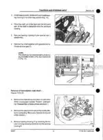
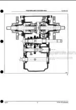
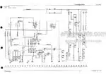
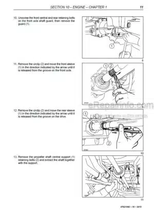
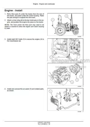
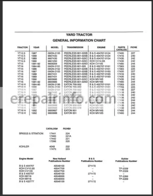
Factory Repair Manual For New Holland TF76, TF78 Combine Harvester. Manual Contains Illustrations, Instructions, Diagrams For Step By Step Remove And Install, Assembly And Disassembly, Service, Inspection, Repair, Troubleshooting, Tune-Ups.
Format: PDF
Language: English
Pages: 577
Number: 604.64.016.00
Bookmarks: Yes
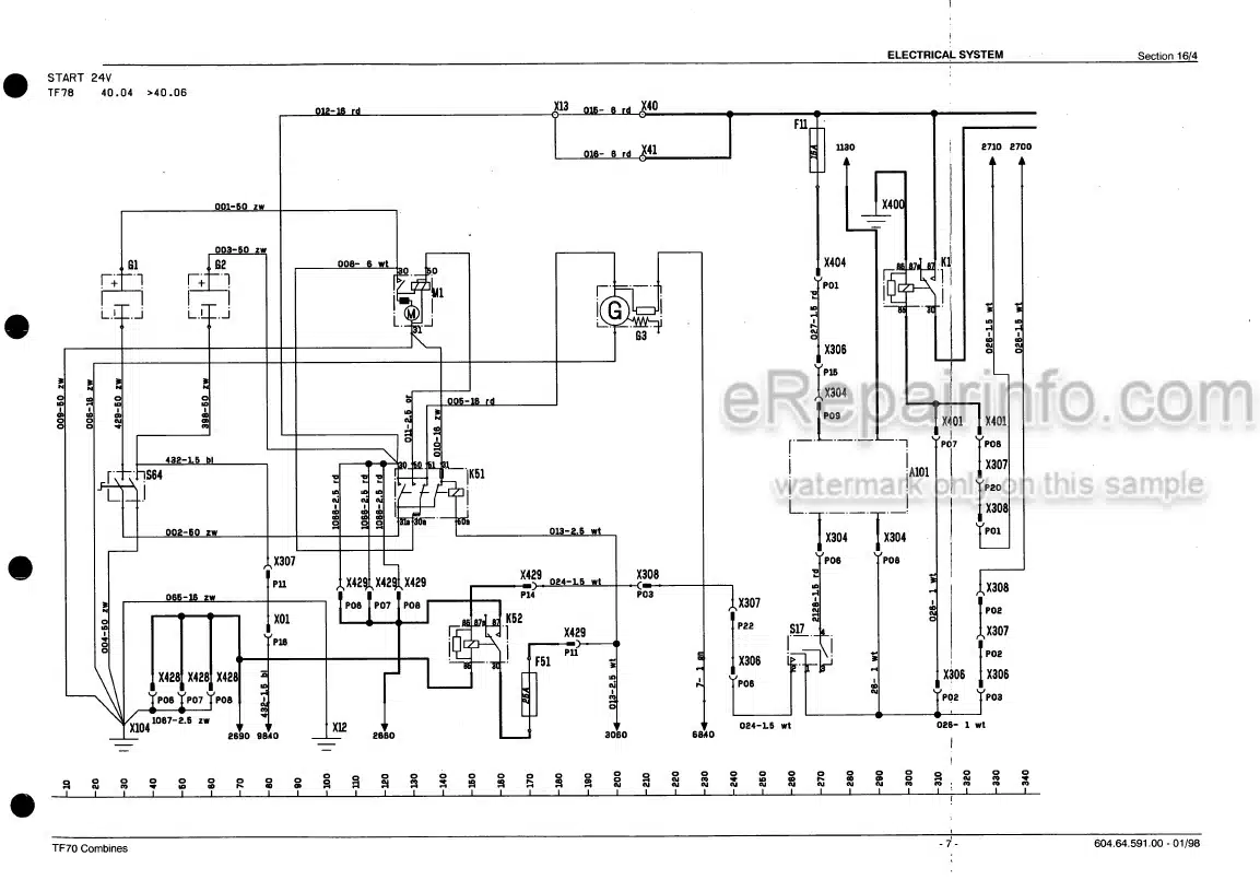
Wiring Diagrams: Yes
Hydraulic Diagrams: Yes
Model
New Holland Combine Harvester
TF76
TF78
Contents
-INTRODUCTION
Explanation Of Machine And Header Serial Numbers
Notes For Service Parts Catalogue Consulting
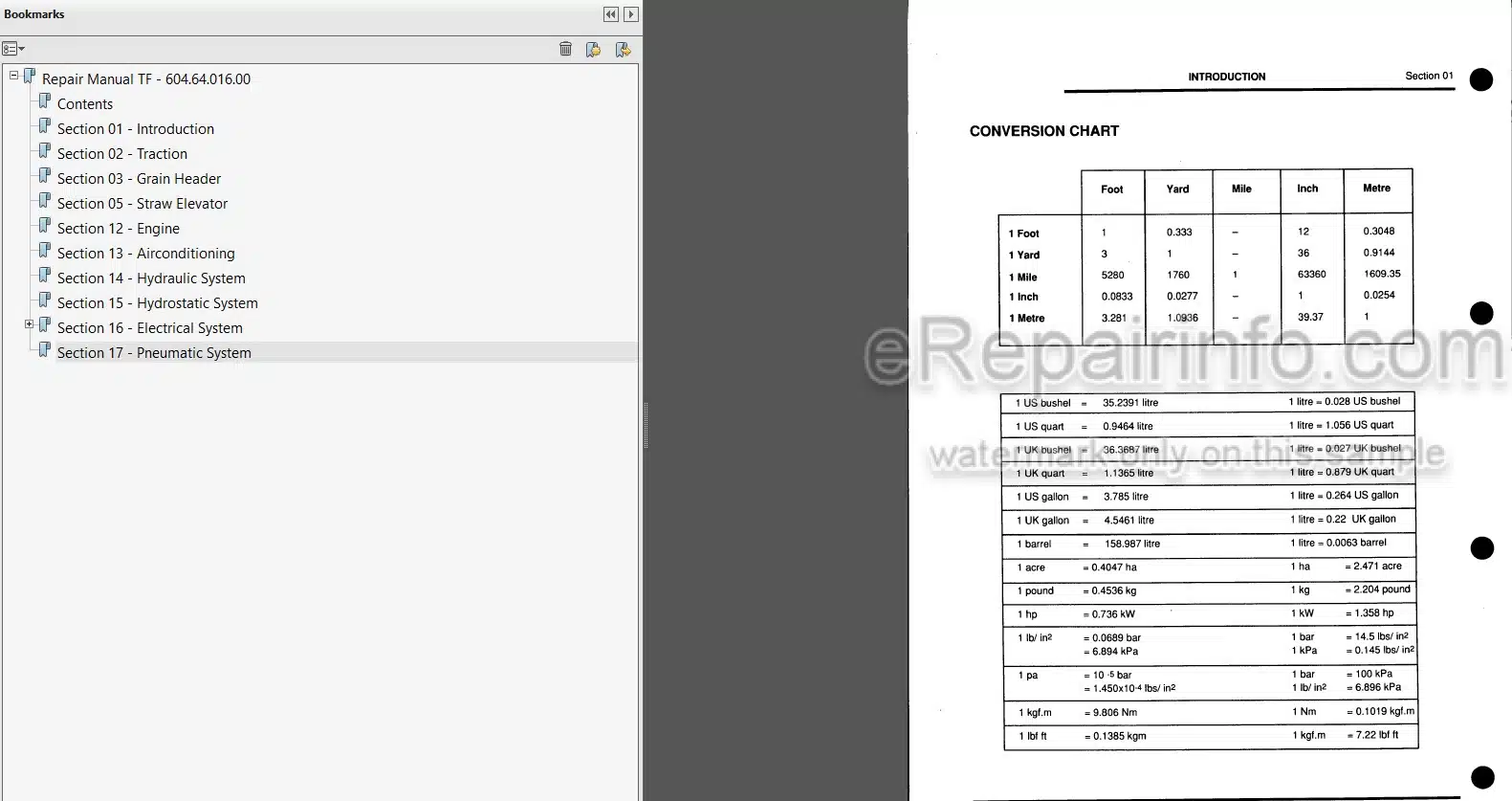
Conversion Chart
Tightening Torques
Speed Ranges
Oil Application Guide
-TRACTION
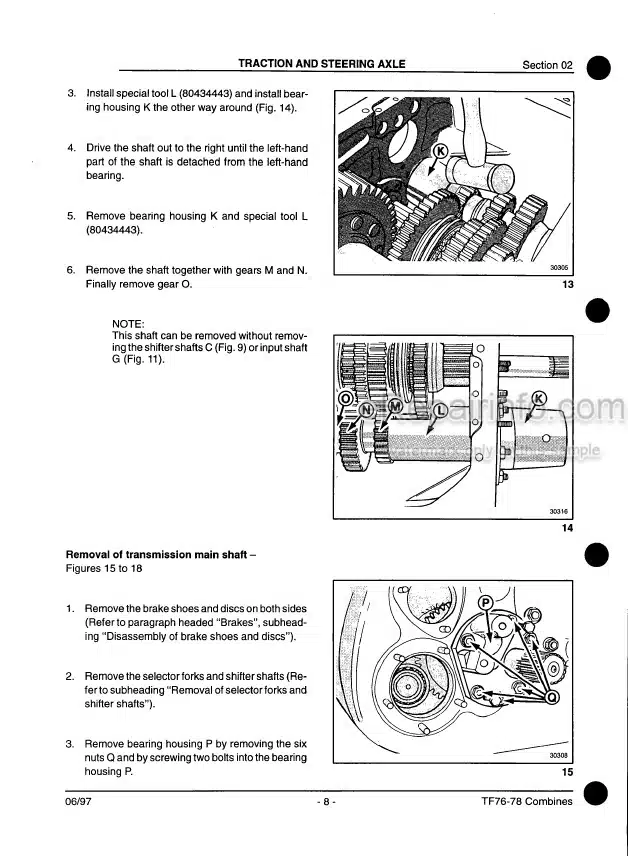
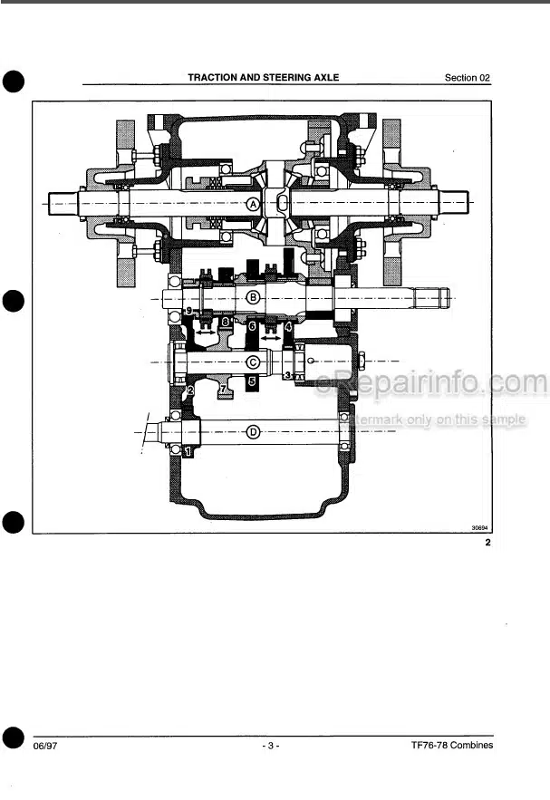
Traction Gearbox
Brakes
Final Drives
Steering Axles
-GRAIN HEADER
Reel Variator Adjustment
Knife And Wobble Box
Feed Auger
Reel Drive
-STRAW ELEVATOR
Straw Elevator Chain
Upper Shaft
Bottom Shaft
Bottom Shaft Height Adjustment
Guide Roll
Reversing System
-ENGINE
IVECO – AIFO 8460 SRI 21 A001 ENGINE
Fuel Injection Pump
Fuel Injectors
Valve Clearance
Cooling System
-AIRCONDITIONING
Airconditioning Circuit
Specifications
Ventilation Unit
Correct Use Of The Air Conditioning System
Storage Maintenance
Compressor Clutch Replacement
-HYDRAULIC SYSTEM
Hydraulic Components And Circuit Diagram
Explanation Of Symbols
Location Of The Main Components
Hydraulic Pump
Header Height Control Valve
Header Suspension Control Valve
High Pressure Relief Valve
Pressure Relief Valve In Lateral Float Circuit
Stack Valves
Hydraulic Steering Valve With Integrated Adapter
Disassembly And Assembly Of The Steering Valve
Hydraulic Cylinders
Reversing System Hydraulic Motor
Hydropneumatic Accumulators
-HYDROSTATIC SYSTEM
Hydrostatic Circuit Diagrams
Explanation Of Symbols
Operation Of The System
Hydrostatic Pump
Hydrostatic Motor
Hydrostatic System Filling-And Start Up Procedure
Powered Rear Wheel Drive
-ELECTRICAL SYSTEM
Introduction
General Information
Location Of Main Components
Circuit Diagrams
Troubleshooting
Software Update
Calibration
-PNEUMATIC SYSTEM
Circuit Diagram
Explanation Of Symbols
Location Of The Main Components
Control Valves
Relief Valve
Compressor
What you get
You will receive PDF file with high-quality manual on your email immediately after the payment.

Reviews
There are no reviews yet.