


Repair Manual For New Holland TN(A) Series Tractors. Illustrations, instructions, diagrams for step by step remove and install, assembly and disassembly, service, inspection, repair, troubleshooting, tune-up.
Format: PDF
Language: English
Pages: 1190
Bookmarks: Yes
Searchable: Yes
Number: 87393902
Wiring Diagrams: Yes
Hydraulic Diagrams: Yes
Model
New Holland TN60A, TN70A, TN75A, TN85A, TN95A
Contents
General
Engine
Clutch
Transmissions
Fwd Transfer Box
Front Axle Mechanical Fwd
Rear Mechanical Transmission
Mechanical Power Take-Off
Braking System
Hydraulic System
Steering
Axles And Wheels
Electrical System
Platform, Cab, Bodywork
-General
General Instructions
Health And Safety
Precautionary Statements
Safety
Ecology And The Environment
Minimum Hardware Tightening Torques
Federal Emissions Warranty
Lubricants And Fluids
-Engine
–Engine (Three-Cylinder)
Special Tools
Tightening Torques
Sectional Views
Engine Troubleshooting
—Overhaul
—-Engine
Removal
Installation
Compression Test
Disassembly
Assembly
—-Checks, Dimensions and Repairs
Cylinder Block
Crankshaft
Main Bearings
Flywheel
Connecting Rods
Pistons
Valves
Tappets
Camshaft
Valve Timing
Cylinder Head
Valve Seats
Valve Guides
Injector Sleeves
Crankshaft Front Oil Seal
Valve/Rocker Arm
—-Exhaust Pipe
Removal
Installation
–Cooling System (Three-Cylinder)
Specifications
Special Tools
Sectional Views
—Description And Operation
—-Cooling System
Radiator
Thermometer
Thermostat
Thermostatic Switch
—Overhaul
—-Coolant Pump
Removal
Installation
Disassembly
Assembly
Drive Belt Tension Adjustment
—- Cooling System Thermostat
Removal
Installation
—-Radiator
Removal
Installation
— Lubrication System (Three-Cylinder)
Specifications
Special Tools
Sectional Views
—Description And Operation
Oil Filter
Low Oil Indicator
Oil Pump
— Fuel System (Three-Cylinder)
Specifications
Special Tools
—Description And Operation
—-Fuel Injection Pump (Bosch)
Turbocharged Models
All Models
—Overhaul
—-Fuel Tank
Removal
Installation
—-Fuel Injectors
Removal
Installation
—-Injection Pump
Removal
—-Lock Timing The Injection Pump On A Workbench (If Needed)
Installation
Check Fuel Injection Pump Timing With Pump Installed On The Tractor
— Engine (Four-Cylinder)
Specifications
—Tightening Torques
Torque Settings With Angles
—Special Tools
—Description And Operation
Sectional Views
—Troubleshooting
—Overhaul
—-Engine
Removal
Installation
—-Compression Test
Disassembly
Assembly
—-Checks, Measurements And Repairs
Cylinder Block
Crankshaft
Connecting Rods
Pistons
Camshaft And Valves
Tappets
Camshaft
Cylinder Head
Crankshaft Front Seal
Crankshaft Rear Seal
Adjusting Valve/Rocker Arm Clearance
— Cooling System (Four-Cylinder)
Specifications
—Description Of Operation
Sectional Views
—Overhaul
—-Coolant Pump
Removal
Installation
—-Thermostart Valve
Removal
Installation
—-Radiator
Removal
Installation
—- Coolant Pump And Alternator Belts
Tension Adjustment
— Lubrication System (Four-Cylinder)
Specifications
—Lubrication System Components
—-Low Oil Pressure Indicator
Functional Checks
—-Oil Filter
Replacement
— Fuel System (Four-Cylinder)
Specifications
Special Tools
—Description And Operation
—-Fuel Injection Pump (Bosch)
Turbocharged Models
All Models
—Overhaul
—-Fuel Injectors
Removal
Installation
—-Bosch Injection Pump
Removal
—-Lock-Timing The Injection Pump
—-Lock Timing The Fuel Injection Pump On A Workbench
Installation
—-Check Fuel Injection Pump Timing With Pump Installed On The Tractor
-Clutch
–Clutch (3-Cylinder Models)
–Specifications
—Models With Mechanical Shuttle
—Models With Power Shuttle
—Tightening Torques
Special Tools
Sectional Views
Luk 11 In/11 In Dual Clutch Pack
Luk 11 In Single Clutch
Pto Servo-Assist Control Valve
—Troubleshooting
—Description And Operation
—-Pto Clutch Servo-Assist Control
Engagement
Disengagement
Adjustment
—Overhaul
—-Clutch
Removal
Disassembly
Assembly
Checks And Repair
Flywheel
Installation
—-Clutch Adjustments
—-Pto Clutch Control Adjustments
–Clutch(4-Cylinder Models)
–Specifications
—Models With Mechanical Shuttle
—Models With Power Shuttle
—Tightening Torques
Special Tools
Sectional Views
Luk 11 In/11 In Dual Clutch Pack
Luk 11 In Single Clutch
Pto Servo-Assist Control Valve
—Troubleshooting
—Description And Operation
—-Pto Clutch Servo-Assist Control
Engagement
Disengagement
Adjustment
—Overhaul
—-Clutch
Removal
Disassembly
Assembly
Checks And Repair
Flywheel
Installation
—-Clutch Adjustments
—-Pto Clutch Control Adjustments
-Transmissions
— Mechanical Transmissions (8 X 8 Non-Synchronized, 12 X 12 Synchro-Command, And 16 X 16 Synchro-Command)
Main Data
Torque Settings
Special Tools
Cross-Sectional Views
Description And Operation
Troubleshooting
Rear Transmission/Gearbox, Removal-Installation
2Rear Transmission/Gearbox, Disassembly-Assembly
Transmission/Gearbox, Driving And Driven Shafts Clearance Adjustments
Gearbox Control Lever, Removal-Installation
Range Gear Control Lever, Removal-Installation
— Power Shuttle Transmission Calibration,Faults And Diagnostics
Fault Codes Indication
—Description Of Systems (Ecm And Cdu)
Automatic Self-Diagnosis (Ecm)
Ecm First Start Up (Self Configuration)
Transmission Disabled Indicator Light
Diagnosis During Operation
Calibration And Diagnostics Unit (Cdu)
Power Shuttle Fault Code Priority
Calibration And Diagnostic Unit Use
Hh Menu Access
H1 – Clutches A And B Calibration
H2 – Clutches A And B Calibration Values Display
H3 – System Configuration
H4 – Power Shuttle Hardware And Software
Revision Levels
H5 – Control Switch Diagnosis
H6 – Clutch A Fill Time Modification And Display
H7 – Clutch B Fill Time
H8 – Erasure Of Data Stored In The Non-Volatile
Memory (Nvm)
H9 – Voltmeter Functions
Ha – Clutch Pedal Potentiometer And Status Switch
Clutch Pedal Potentiometer Replacement And Clutch
Pedal Switch Adjustment
Hc – Transmission Oil Temperature Sender
Hd – Hi/Lo Synchronizer Operation
He – Gear Change Adjustments
Hf – Stored Error Codes
Troubleshooting Fault Codes
—Description Of Systems (Ecm And Est)
Automatic Self-Diagnosis (Ecm)
Ecm First Start Up (Self Configuration)
Transmission Disabled Indicator Light
Diagnosis During Operation
Power Shuttle Fault Code Priority
Electronic Service Tool (Est)
Downloading The Latest Software Into
Tna Series Tractor Power Shuttle Control
Module With The Electronic Service Tool
Connecting The Electronic Service Tool
(Est) To The Tractor
H1 – Clutches A And B Calibration
H2 – Clutches A And B Calibration Values Display
H3 – System Configuration
H4 – Power Shuttle Hardware And Software
Revision Levels
H5 – Control Switch Diagnosis
H6 – Clutch A Fill Time Modification And Display
H7 – Clutch B Fill Time
H8 – Erasure Of Data Stored In The Non-Volatile
Memory (Nvm)
H9 – Voltmeter Functions
Ha – Clutch Pedal Potentiometer And Status Switch
Clutch Pedal Potentiometer Replacement And Clutch
Pedal Switch Adjustment
Hc – Transmission Oil Temperature Sender
Hd – Hi/Lo Synchronizer Operation
He – Gear Change Adjustments
Hf – Stored Error Codes
Troubleshooting Fault Codes
Fault Codes
Power Shuttle (16 X 16) Electronic Control Module
Input/Output Wiring Diagram
– Fwd Transfer Box
— Fwd Transfer Box
Main Data
Torque Settings
Tools
Cross-Sectional Views
Description And Operation
Troubleshooting
Drive Shafts And Guard, Disassembly – Assembly
Drive Gear Housing Assembly, Removal – Installation
Drive Gear Housing Assembly Removed, Disassembly – Assembly
Drive Gear Housing Assembly Removed, Disassembly – Assembly
– Front Axle Mechanical Fwd
— Front Axle
Main Data
Tools
Tightening Torques
Sectional Views
Description And Operation
Troubleshooting
Mechanical Pto Assembly – Removal-Installation
– Braking System
— Braking System
Main Data
Torque Settings
Cross-Sectional Views
Tools
Description And Operation
Troubleshooting
Right Or Left-Hand Brake Removal-Installation
Brake Hydraulic Pump Removal-Installation
Brake Hydraulic System Air Bleeding
Parking Brake Brake Disks Removal-Installation
Handbrake Control Stroke Adjustment
— High Pressure System Description And Operation
Precautionary Statements
Description And Operation
High-Pressure System Hydraulic Pump
Hydraulic System Configuration Table
Mechanically Controlled Hydraulic Lift
Lift-O-Matic
Hydraulic Power Lift (Hpl) Control Valve Oil Flow
Remote Control Valves
Rear Remote Valve Arrangement
Rear Remote Valve Stacking
Rear Remote Valve Control Levers
Deluxe Quick-Fit Couplers
Zero-Pressure Return Port
Mid-Mount Control Valves (Optional)
Switching Between Single And Double Acting Cylinders
Single Or Double Acting Valve With Automatic Detent Release And Float
Double-Acting Valve Less Automatic Detent Release And Float
Single-Acting Valve Less Automatic Release And Float
Tn60A, Tn70A, And Tn75A Series Hydraulic System Diagram
— High Pressure System Overhaul And Adjustment
Specifications
Torque Settings
Hydraulic Lift Tools
Cross-Sectional Views
Hydraulic Lift Troubleshooting
Mechanically Controlled Lift Internal Controls Disassembly-Assembly
Mechanically Controlled Lift Adjustments
Mechanically Controlled Lift Rod Mechanism Adjustments
Lift Arm Descent Speed Adjustments
Upper Stroke Limit Adjustment
Adjusting The Upper Stroke Limit Of The Lift-O-Matic Device
Arm Shaft And Lift Cylinder Disassembly-Assembly
Mechanically Controlled Lift Control Valve Disassembly-Assembly
Lift Pressure Relief Valve Removal-Installation
Lift Pressure Relief Valve (Calibration)
High Pressure (Lift) Pump Disassembly-Assembly
— Low-Pressure System Description And Operation
Low-Pressure, Steering And Lubrication System – General Description
Low-Pressure Oil Flow
Transmission Lubrication System
Steering System Oil Flow
Electro-Hydraulic Four-Wheel Drive (Fwd) For Models With 40 Kph Transmissions
— Low-Pressure System Test Fitting Locations
System Test Fitting Locations
– Steering
— Steering
Main Data – Torque Settings – Tools
Description And Operation
Components
Troubleshooting
Hydrostatic Steering Wheel, Removal – Installation
Hydrostatic Steering Control Valve, Removal – Installation
Hydrostatic Steering Control Valve, Disassembly – Assembly
Hydrostatic Steering Control Valve – Bench Testing
Steering Control Cylinder, Removal – Installation
Steering Control Cylinder, Disassembly – Assembly
–Open Center Flow Gear Pump
Main Data
Torque Settings
Description And Operation
Hydrostatic Steering Oil Pump – Disassembly-Assembly (With Unit Removed)
– Axles And Wheels
— Axles And Wheels
Main Data
Cross-Sectional Views
Torque Settings
Tools
Troubleshooting
Front Axle Hub Disassembly-Assembly
Front Axle Removal-Installation
Stub Axle Overhaul
Checking The Alignment Of The Front Wheels (Toe-In)
– Electrical System
–Instruments
Analog Instruments
Indicator Light Panel
—Transmitters, Sensors And Switches
Maintenance
— Starting System
Specifications
Tightening Torques
Description And Operation
Troubleshooting
—Test And Check
Starting System Test On Tractor
Current Absorbed On The Starter Motor Circuit
—-Starting System Circuit Resistance (Voltage Drop)
Positive Battery Cable
Starter Motor Ground Connections
Battery Ground Lead
—Overhaul
—-Starter Motor
Removal
Disassembly
Assembly
Testing Starter Motor
— Charging System
Specifications
Tightening Torques
Description And Operation
—Troubleshooting
—-Precautions
Preliminary Checks
Battery Check
Driving Belt Check
Fan Belt Tensioner
Preliminary Tests
Warning Light Check
Alternator Wire Connection Tests
Charging Current And Regulated Voltage Tests
Charging Circuit Voltage Drop Tests
Ground Side Voltage Drop Test
Maximum Alternator Output Test
Alternator Component Tests
—Overhaul
—-Alternator
Removal
Stator Windings Continuity Check
Diode Excitation Test
Positive Power Diode Test
Negative Power Diode Test
Rotor Tests
Disassembly
Electronic Voltage Regulator
Assembly
Installation
–Battery
Specifications
Description And Operation
—Overhaul
—-Battery
Removal
Installation
Battery Maintenance
Relative Density
—Battery Maintenance
Dry-Charged Batteries
Charging The Battery
Normal Charging (Top Up)
Charging Extremely Flat Batteries
—-Tests
Performance Test
—Battery Problems – Frequent Causes
— Connectors
Electrical Circuit Connectors/Component Connectors Identification
Wire Color Coding
Connector Location Points
Connectors / Component Connectors / Pin Locations
— Electrical Components
—Overhaul
—-Indicator Panel
Removal
Installation
—-Power Shuttle Electronic Control Unit
Removal
Installation
—-Fusebox Replacement
Removal
Installation
—-Fuses
Replacement
—-Relay
Replacement
— Wiring Diagrams
How To Use Wiring Diagrams
2Wd / Power-Shuttle Transmission Configuration / 3-Cylinder
Mechanical 4Wd / Power-Shuttle Transmission Configuration / 3-Cylinder
Electro-Hydraulic 4Wd (40 Kph Only) / Power-Shuttle Transmission Configuration /3-Cylinder
2Wd / Mechanical Shuttle Transmission Configuration / 3-Cylinder
Mechanical 4Wd / Mechanical Shuttle Transmission Configuration / 3-Cylinder
Electro-Hydraulic 4Wd (40 Kph Only) / Mechanical Shuttle Transmission Configuration/ 3-Cylinder
2Wd / Power-Shuttle Transmission Configuration / 4-Cylinder
Mechanical 4Wd / Power-Shuttle Transmission Configuration / 4-Cylinder
Electro-Hydraulic 4Wd (40 Kph Only) / Power-Shuttle Transmission Configuration /4-Cylinder
2Wd / Mechanical Shuttle Transmission Configuration / 4-Cylinder
Mechanical 4Wd / Mechanical Shuttle Transmission Configuration / 4-Cylinder
Electro-Hydraulic 4Wd (40 Kph Only) / Mechanical Shuttle Transmission Configuration / 4-Cylinder
Symbols Used In Electrical Diagrams
-Platform, Cab, Bodywork
–Bodywork
—Overhaul (Removal / Installation)
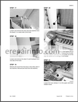
—-Hood Panel
—-Protective Grill
—-Dashboard
—-Rops (Roll Over Protection Structure)
—-Fenders
—-Platform
What you get
You will receive PDF file with high-quality manual on your email immediately after the payment.


Reviews
There are no reviews yet.