


Repair Manual For New Holland TV140 Tractor. Illustrations, instructions, diagrams for step by step remove and install, assembly and disassembly, service, inspection, repair, troubleshooting, tune-up.
Format: PDF
Language: English
Pages: 2494
Bookmarks: Yes
Searchable: Yes
Number:
Wiring Diagrams: Yes
Hydraulic Diagrams: Yes
Model
New Holland TV140
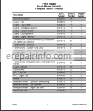
Contents
- – General Information
Precautionary Statements
Safety Precautions
General Considerations
Tractor Identification
Engine Identification
Service Techniques
Minimum Hardware Tightening Torques
Standard Torque Data
Recommended Lubricants And Coolants
Recommended Sealants - – Engine Systems
Air Induction System
Bolt Torque Specifications
Air Induction System Description And Operation
Component Operation
Turbocharger Boost Testing
Air Induction SystemRemoval And Repair Of Components
Turbocharger Intake Tube
Turbocharger Outlet Tube
Air Filter Housing, Precleaner, And Air Induction Scoop
Turbocharger
Repair Time Schedule
Exhaust System
Bolt Torque Specifications
Exhaust System Description Of Operation
Exhaust System Component Removal And Repair
Exhaust Muffler And Stack
Repair Time Schedule
Engine Specifications
Cylinder Head Assembly
Camshaft Assembly
Connecting Rods
Pistons
Manifolds
Cylinder Block Assembly
Timing Gears
Lubrication System
Troubleshooting
Dynamometer Engine Testing
Dynamometer Engine Break In
Compression Test
Engine Overhaul
Engine Removal
Engine Disassembly
Engine Component Disassembly, Inspection, And Assembly
Front Timing Gears, Oil Pan, Camshaft, And Valve Tappets (Lifters)
Pistons And Connecting Rods
Crankshaft And Main Bearings
Oil Pump And Sump Tube
Oil Cooler/Filter Support Assembly
Flywheel
Engine Assembly
Engine Installation
Repair Time ScheduleEngine Overhaul
Cooling System
Bolt Torque Specifications
Cooling System Description And Operation
Individual Component Operation
Cooling System Troubleshooting
Cooling System Testing
Cooling System Tests
Cooling SystemRemoval And Repair Of Components
Radiator
Thermostat
Cooling Fan (North American Models)
Cooling Fan And Viscous Clutch (International Models)
Fan Belt Tensioner
Water Pump
Repair Time ScheduleCooling System
Type
Air Filter Configuration
Primary
Secondary
Manufacturer
Model
Bearing Type
Maximum Boost Pressure - – Transmissions
Introduction
Orientation
Splitter Box
Hydrostatic Drive Description
Safety
Power Flow
Description Of Operation
Splitter Box Description
Splitter Box Gear Sets
Hydrostatic And Hydraulic System Components
Hydrostatic Drive Description
Moving A Disabled Tractor
Troubleshooting And Testing
Pressure Testing
Range Select Control Switch And Valve
Splitter Box
Auxiliary Pump
Auxiliary Drive Housing
Auxiliary Couplers
Articulation Joint Drive Shafts
Upper Drive Shaft
Engine Power Input Shaft
Lower Drive Shaft
Splitter Box Power Input (Top) Shaft
Splitter Box Power Output (Bottom) Shaft
EngineEnd Axle Drive Shaft
Splitter Box
Tapered Bearing End Play Check And Adjustment
Hydrostatic Motor
Hydrostatic Pump
Fnr Lever Cables
Repair Time Schedule - – Engine End Axle
Axle Shaft Preload
Axle Shaft Spacer Selection Table
Differential Bearing Preload
Differential Bearing Shim Table
Drive Pinion Preload
Drive Pinion Spacer Table
Tightening Torques
Drive Path
Drive Pinion
Axle Shaft And Trumpet Housing
Differential Lock
Troubleshooting
Trumpet/Axle Disassembly
Planetary Disassembly
Planetary Inspection
Planetary Reassembly
Planetary Ring Gear Removal
Planetary Ring Gear Installation
Trumpet/Axle Inspection
Trumpet/Axle Reassembly
Pinion Gear Removal
Pinion Gear Disassembly
Pinion Gear Inspection
Center Housing Inspection
Pinion Gear Reassembly
Pinion Bearing Preload
Drive Pinion Spacer Table
Pinion Gear Installation
Differential Disassembly
Differential Inspection
Differential Reassembly
Differential Bearing Preload
Differential Bearing Shim Table
Differential Lock Internal Operating Components Overhaul
Differential Lock Valve And Tube Removal
Differential Lock Valve And Tube Inspection
Differential Lock Valve And Tube Installation
Oscillating Components
Rear Trunnion Inspection
Rear Trunnion Installation
Front Trunnion Removal
Front Trunnion Inspection
Front Trunnion Installation
Diff Lock Switch Removal
Diff Lock Switch Inspection
Diff Lock Switch Installation
Apply Solenoid And Valve Removal
Apply Solenoid And Valve Inspection
Apply Solenoid And Valve Installation
Breather Removal
Breather Inspection
Breather Installation
Repair Time Schedule - – Cab End Axle
Repair Time Schedule - – Power TakeOff
Cab End Pto Clutch Control Valve Operation
Cab End Output Drive
Electrical Operation
Cab End Pto Electrical Circuit
Troubleshooting
Disassembly And Repair
Preliminary Procedures
Cab End Pto Clutch
Cab End Pto Shafts And Gears
Pto Switch - – Brakes
Brake Disc Components
Foot Pedal Linkage
Master Cylinder
Reservoir
Hose Reservoir To Master Cylinder
Tubes Pressure Supply
Park Brake Lever
Park Brake Cables And Links
Brake Pedal Switch
Park Brake Switch - – Hydraulic Systems
Auxiliary Hydraulics
Component Identification
Hydraulic Circuits
Description Of Operation
Steering Control Valve
Troubleshooting And Testing
Disassembly And Repair
Implement Pump
Implement Valve
Priority (Inlet) Valve Section
Tan (Float) Valve Section
Blue (Detent) Valve Section
Green (Standard) Valve Section
Implement Valve
Implement Valve Control Linkage
Control Lever Cable
Control Pedal Assembly
Control Pedal Cable
Steering Control Valve
In Cab Flow Control Cables
Hydraulic System Hoses
Hydraulic Oil Heater
Engine End Remote Valves
Hydraulic Oil Cooler
Hydraulic Oil Cooler ByPass - – Wheels, Tires, And Ballasting
Proper Jacking
Tire Inflation
Tire And Wheel Options - – Frames
Engine Hood
Hood Support Assembly
Side Panels, Right Hand And Left Hand
Front Grille
Cab End Fenders
Left Hand And Right Hand
Engine End Fenders
Left Hand And Right Hand
Heatshield
Engine End Drawbar
Cab End Drawbar
Front Axle Support
Frame Side Rails
Steering Pins
Pivot Pins
Front Frame
Rear Frame - – Climate Control
Description And Operation
Refrigerant Information
The Basics Of Refrigeration
Individual Component Operation
Compressor And Clutch
Condenser
ReceiverDrier
Thermal Expansion Valve
Evaporator/Heater Assembly
Blower Motor Assembly
Thermostatic Switch
High And Low Pressure Switches
Heater Control Valve
Switched Power: Fuses And Hvac Relay
Air Filtration
Troubleshooting And Testing
General Safety And Service Precautions
Recovering RA Refrigerant With Oem
System Evacuation And Recharging With Oem
Oil Level Check Or Adjustment
Leak Detection
Performance Testing
Pressure/Temperature Relationship Chart
Conditions For Performance Testing
Gauge Readings And Interpretations
Performance Test And Diagnosis Summary
General Troubleshooting Summary
Heating System
Air Conditioning System
Air Conditioning Component
Thermal Expansion Valve
Evaporator/Heater Assembly
Condenser
High And Low Pressure Switches
Compressor
Compressor Clutch
Receiver Drier
Air Conditioning Hoses
Heater Control Valve
Recirculation Door Control
Blower Speed Control
Heater Hoses
Repair Time Schedule - – Electrical System
Electrical System
Using Schematics
Circuit Troubleshooting
Temporary Wiring Harness Repair
Description Of Operation
Batteries
Starting And Charging Systems
Starter
Batteries Troubleshooting
Starter Troubleshooting
Eics Error Codes
Eics Connector Chart
Alarms
ThreePoint Hitch Controller - – Accessories
Electrical Kits And Accessories
Frame And Platform
Hydraulic And Pto Kits
Loader Kits And Accessories - – Cab
Cab Mounts
Cab
Cab Roof
Taillight Panel
Cab Fenders
Wiper Motor Cover
Windshield Wipers
Doors
Cab Door Lock And Latch
Lock Cylinder
Window Latch
Door Glass
Side Windows
Floor Mats
Seat Console
Fender Well Covers
Seat
Console Assembly
Steering Logic Valve Trip Linkage
Rotating Grommet Assembly
Headliner
Louvers
Radio And Speakers
Calibration (Adjustments)
What you get
You will receive PDF file with high-quality manual on your email immediately after the payment.


Reviews
There are no reviews yet.