


Factory Workshop Manual For Perkins 102-05 103-07 103-10 103-13 103-15 104-19 104-22 engines. Tons of illustrations, instructions, diagrams for step by step remove and install, assembly and disassembly, service, inspection, repair, troubleshooting, tune-ups.
Format: PDF
Language: English
Pages: 144
Number: TPD1377E
Searchable: Yes
Wiring Diagrams: Yes
Model
Perkins
102-05, 103-07, 103-10, 103-13, 103-15, 104-19, 104-22
102-05 Two cylinder diesel engines
103-07 Three cylinder diesel engines
103-10
103-13
103-15
104-19 Four cylinder diesel engines
104-22
Contents
-GENERAL INFORMATION
Introduction
Safety Precautions
Engine Preservation
Powerpart Recommended Consumable Products
Engine ID Location
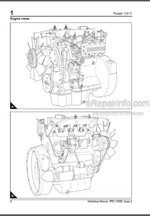
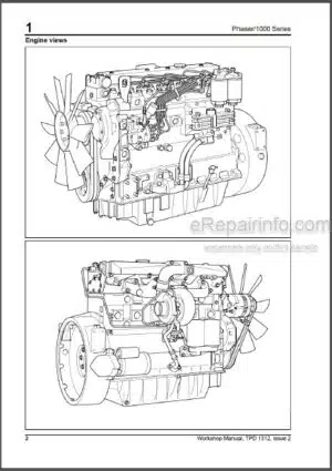
Engine Views – 3 Cylinder Front And Rear
Engine Views – 2 Cylinder Front And 4 Cylinder Front
Engine Lift Equipment
Viton Seals
Safety Cautions, When An Engine Is Cleaned
Engines That Conform To Emissions Levels
Compression Test Data
-SPECIFICATIONS
Basic Engine Data
Thread Sealant
Recommended Torque Tensions
Data And Dimensions
Injection Timing
Cylinder Bore Dimensions
Piston And Piston Ring Dimensions
Gudgeon Pin
Crankshaft Deflection
Crankshaft Inspection
Crankshaft Journal Diameters
Crankshaft Pin Diameters
Bearing Holder
Undersize Bearing Shell Chart
Crankshaft Bearing Bush
-CYLINDER HEAD ASSEMBLY
Rocker Cover And Inlet Manifold
Rocker Assembly
Rocker Shaft (102-05, 103-07, 103-10)
Rocker Shaft (103-13, 103-15, 104-19, 104-22)
Fan And Mounting
Exhaust Manifold And Gasket
Fuel Injection Pipes / Fuel Return Pipes
Oil Pipes
Atomisers
Busbar / Glowplugs
Head Bolts
Cylinder Head Gasket
Head Bolts – All Variants
Valve And Valve Springs
Valve Spring
Valve Stem Diameter And Thickness Of Valve Head
Valve Guide Clearance
Cylinder Head
Valve Seat Width
Valve Depth
Valve Seat Contact Face
Valve Tip Clearance
-PISTON AND CONNECTING ROD ASSEMBLIES
Big End Bearing And Cap
Piston And Connecting Rod
Piston And Piston Ring
Piston Ring And Block
Small End Bush
Connecting Rod
-CRANKSHAFT ASSEMBLY
Crankshaft Pulley
Flywheel, Backplate And Oil Seal
Crankshaft Retainer Setscrews And Crankshaft
Bearing Clearance
Main Bearings
-TIMING CASE AND DRIVE ASSEMBLY
Fuel Injection Pump
Timing Cover
Slider
Camshaft Retainer Plate
Camshaft And Cam Followers
Camshaft Assembly
Max Fuel Screw And Max Speed Screw
Idler Gear And Oil Pump
Idler Hub
Gear Teeth Backlash
Oil Pump End Float
Governor Spring
Oil Seal Protector
Timing Cover
-CYLINDER BLOCK ASSEMBLY
Front Bush
Cylinder Block Top Face
-ENGINE TIMING
Fuel Injection Pump Timing
-ASPIRATION SYSTEM
Breather System
-LUBRICATION SYSTEM
Oil Filter Canister
Pressure Relief Valve
Lubricating Oil Sump
Strainer And Suction Pipe
Lubricating Oil Pump
Oil Pressure Switch
-FUEL SYSTEM
Atomizers
Fuel Lift Pump
Fuel Injection Pump
Vent Points
-COOLING SYSTEM
Fan And Mounting
Coolant Pump
Thermostat
-FLYWHEEL AND HOUSING
Flywheel
Flywheel Housing (If Fitted)
-Electrical Equipment
Electrical Shut Off Solenoid (Esos)
Alternator
Starter Motor
Wiring Diagram 14 And 15 Amp Alternator – 102-05, 103-07, 103-10
Wiring Diagram 40 Amp Alternator – 103-10 (When Fitted With Optional Alternator)
Wiring Diagram 55 Amp Alternator – 103-15, 104-19, 104-22
Wiring Diagram 40 Amp Alternator – 103-13124
Auto Shutdown Wiring Diagram125
Auto Shutdown Wiring Diagram 14 And 15 Amp Alternator – 102-05, 103-07, 103-10
Auto Shutdown Wiring Diagram 40 Amp Alternator – 103-10 (When Fitted With Optional Alternator)
Auto Shutdown Wiring Diagram 40 Amp Alternator – 103-13
Auto Shutdown Wiring Diagram 40 Amp Alternator – 103-15, 104-19, 104-22
-AUXILIARY EQUIPMENT
Radiator Anti-Vibration Mountings
-SPECIAL TOOLS
Special Tools List
What you get
You will receive a PDF file with a high-quality manual on your email immediately after the payment.


Reviews
There are no reviews yet.