


Factory Workshop Manual For Perkins 700 Series UA UB UC engines. Tons of illustrations, instructions, diagrams for step by step remove and install, assembly and disassembly, service, inspection, repair, troubleshooting, tune-ups.
Format: PDF
Language: English
Pages: 206
Number: TPD1392E
Searchable: Yes
Model
Perkins 700 Series UA, UB, UC
Four-cylinder naturally aspirated and turbocharged
diesel engines
Contents
-GENERAL INFORMATION
Introduction
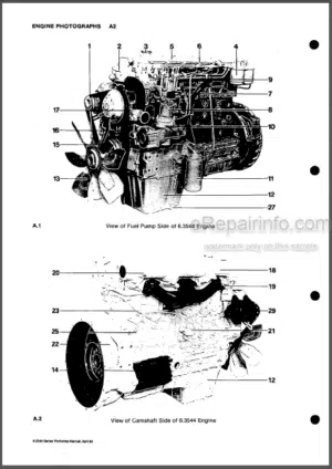
Engine Views – Naturally Aspirated Engine
Engine Views – Turbocharged Engine
Engine ID Location
Safety Precautions
Viton Seals
Engine Lift Equipment
Powerpart Consumable Products
-SPECIFICATIONS
Basic Engine Data
Data And Dimensions
Thread Sealant
Recommended Torque Tensions
Compression Test Data
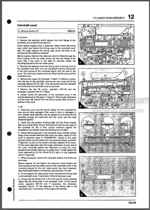
-CYLINDER HEAD ASSEMBLY
Rocker Cover
Rocker Assembly (Latest Engines)
Rocker Assembly (Earlier Engines)
Rocker Shaft (Latest Engines)
Rocker Shaft (Earlier Engines)
Valve Tip Clearance
Valve Springs (With Cylinder Head Fitted)
Exhaust / Induction Manifolds And Gasket
Cylinder Head Setscrews
Cylinder Head Gasket
Valve And Valve Springs
Valve Stem
Valve Depth
Valve Guides
Valve Seats
Valve Seat Insert
Cylinder Head
-PISTON AND CONNECTING ROD ASSEMBLIES
Big End Bearing And Cap
Piston And Connecting Rod
Piston And Piston Rings
Piston Rings
Connecting Rod
Small End Bush
Piston Height Above The Cylinder Block
Piston Cooling Jets (Uc Engines)
-CRANKSHAFT ASSEMBLY
Crankshaft Pulley
Rear Oil Seal
Thrust Washers And Crankshaft End-Float
Thrust Washers
Main Bearing Caps (With Crankshaft In Position)
Main Bearings
Main Bearing Caps (Front And Rear)
Crankshaft
Wear Sleeve
-TIMING CASE AND DRIVE ASSEMBLY
Tamper Proof Screws
Timing Case
Gear Teeth Meshing
Front Oil Seal
Idler Gear
Idler Gear Bushes
Idler Gear Hub
Camshaft Assembly For The Fuel Injection Pump
Camshaft Assembly And Tappets For The Valves
Camshaft Assembly For The Valves
Crankshaft Gear
Backplate
-CYLINDER BLOCK ASSEMBLY
Cylinder Block Bores
Camshaft Bores
-ENGINE TIMING
To Set Approximately Number 1 Piston To Tdc On The Compression Stroke
Fuel Injection Pump Timing
-ASPIRATION SYSTEM
Turbocharger
Impeller And Compressor Casing
Engine Breather Assembly
-LUBRICATION SYSTEM
Oil Filter Canister
Engine Lubricating Oil
Filter Head And Oil Cooler
Aluminium Sump
Steel Sump
Oil Strainer And Suction Pipe
Lubricating Oil Pump
Relief Valve
-FUEL SYSTEM
Fuel Filter Element
Atomiser Fault
High Pressure Fuel Pipes
Leak Off Rail
Atomisers
Fuel Lift Pump
Fuel Injection Pump
Governor Weight Assembly
Speed Control Lever Assembly
To Change A Plain Bush To A Threaded Bush
Fuel Injection Pump Linkage
To Record The Maximum Fuel Position Of The Fuel Control Rack
How To Use The Reference Setting For Maximum Fuel
-COOLING SYSTEM
Coolant
Thermostat
Fan
Coolant Pump
Oil Cooler
-FLYWHEEL AND HOUSING
Flywheel
Starter Ring
Flywheel housing
-ELECTRICAL EQUIPMENT
Drive Belt
Alternator
Glowplugs (Starting Aid)
Starter Motor
Electrical Stop Solenoid
-AUXILIARY EQUIPMENT
Power Take-Off Assembly
-SPECIAL TOOLS
Special Tools List
What you get
You will receive PDF file with high-quality manual on your email immediately after the payment.


Reviews
There are no reviews yet.