Factory Service Manual For Sperry New Holland TR75-85 Combine. Manual Contains Illustrations, Instructions, Diagrams For Step By Step Remove And Install, Assembly And Disassembly, Service, Inspection, Repair, Troubleshooting, Tune-Ups.
Format: PDF
Language: English
Pages: 423
Number: 40007520
Bookmarks: Yes
Wiring Diagrams: Yes
Model
Sperry New Holland Combine
TR75 TR85
Contents
-BRAKE SYSTEM
Brake Drum And Shoes – Style I Transmission
Hydraulic System
Introduction
Labor Guide
Slave Cylinders – Style I Transmission
-CLEANING SYSTEM
Cleaning Fan Removal
Cleaning Fan Shaft Installation
Cleaning Shaft Removal Only
Introduction
Labor Guide
Shoe
Shoe Bushing Tightening Sequence
-CLUTCH HYDRAULIC ACTUATION SYSTEM
Bleeding
Clutch Adjustment
Introduction
Labor Guide
Master Cylinder
Pedal Adjustment
Slave Cylinder
-CONCAVES
Concave And H-Frame Adjustment
Concave Installation
H-Frame
H-Frame Parts
Installation
Introduction
Labor Guide
-DIFFERENTIAL – STYLE I TRANSMISSION
Assembly
Disassembly
Installation
Labor Guide
Parts List
Removal
Specifications
Torque Values
-DISCHARGE BEATER AND GRATE
Discharge Beater
Discharge Beater Grate
Introduction
Labor Guide
Removal Of The Discharge Beater – Style I
Removal Of The Discharge Beater – Style Ii
-ELECTRICAL SYSTEM
Assembly
Component Location
Electrical Charging System
Engine Starting System (Tr85)
General Location Of Components
Introduction
Normal Operation Of Electrical System
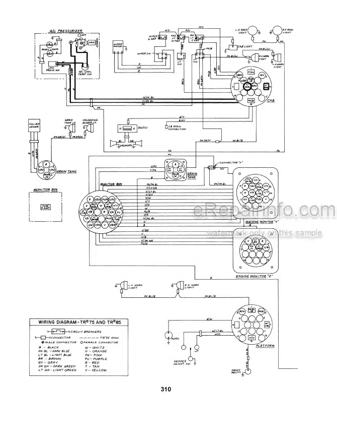
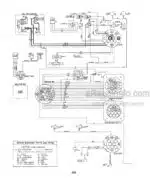
Using The Wiring Diagram
-FINAL DRIVE
Final Drive Installation
Final Drive – 32″ Wheels
Final Drive – 26″ Wheels
Introduction
Labor Guide
Safety
-GENERAL INFORMATION
-GROUND DRIVE TRANSMISSION-STYLE I
Disassembly (Installed On Machine)
Disassembly (Removed From Machine)
Introduction
Labor Guide
Lubrication
Removal Of Style I
Service Of Transmission Components
Specifications
Torque Values
-GROUND DRIVE TRANSMISSION – STYLE II
Assembly
Brake And Differential Parts
Differential Parts
Disassembly
Introduction
Labor Guide
Removal
Tools Needed
Transmission Parts
-HYDRAULIC SYSTEM
AHHC Valve Operation
AHHC Valve Parts
Assembly
Automatic Head Height Control Operation
Automatic Head Height Control Valve Service
Auxiliary Functions
Bladder Accumulator Operation
Directional Control Valve Operation
Directional Control Valve Parts
Directional Control Valve Repair
Directional Control Valve Trouble Shooting
Double-Acting Lockout Plunger
Head Height Control Trouble Shooting
Head Lift Cylinder Repair
Hydraulic Pump Parts List
Hydraulic System Function
Hydraulic System Pressure Testing
Inspect Parts For Wear
Introduction
Labor Guide
Meter (Gerotor) End
Placing Pump Back Into Service
Precharging And Recharging
Pump Repair
Pump Trouble Shooting
Secondary System Relief Valve Parts
Secondary System Relief Valve Repair
Single-Acting Lockout Plunger
Steering And Traction Vari-Drive Cylinder Repair
Steering Control Operation
Steering Control Unit
Steering Control Unit Parts
Steering System Trouble Shooting
Unloading Auger Cylinder Repair
-HYDROSTATIC TRACTION DRIVE
Charge Pump Repair Procedures
Disassembly
Explanation Of Terms Used In Failure Analysis
Hydrostatic System Specifications
Hydrosatic Transmission Components
Hydrostatic Transmission Repair Procedures
Hydrostatic Transmission Service Tools Needed
Instructions For Parts Evaluation
Introduction
Labor Guide
Other Information
Rotating Group Component Inspection
Rotating Group Parts
System Components Function And Adjustment
System Function
Troubleshooting
Trouble Shooting Chart
-LOADING AND UNLOADING SYSTEMS
Belt Installation
Belt Removal
Driven Sheave Removal
Grain Tank Cross Auger Service
Labor Guide
Left Side Drive Belt
Loading System
Unloading Auger Removal
Unloading Auger Slip Clutch Service
Unloading Auger U-Joint Service
Unloading System
-MAIN SHAFT
Assembly
Disassembly
Installation
Labor Guide
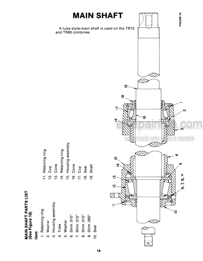
Parts List
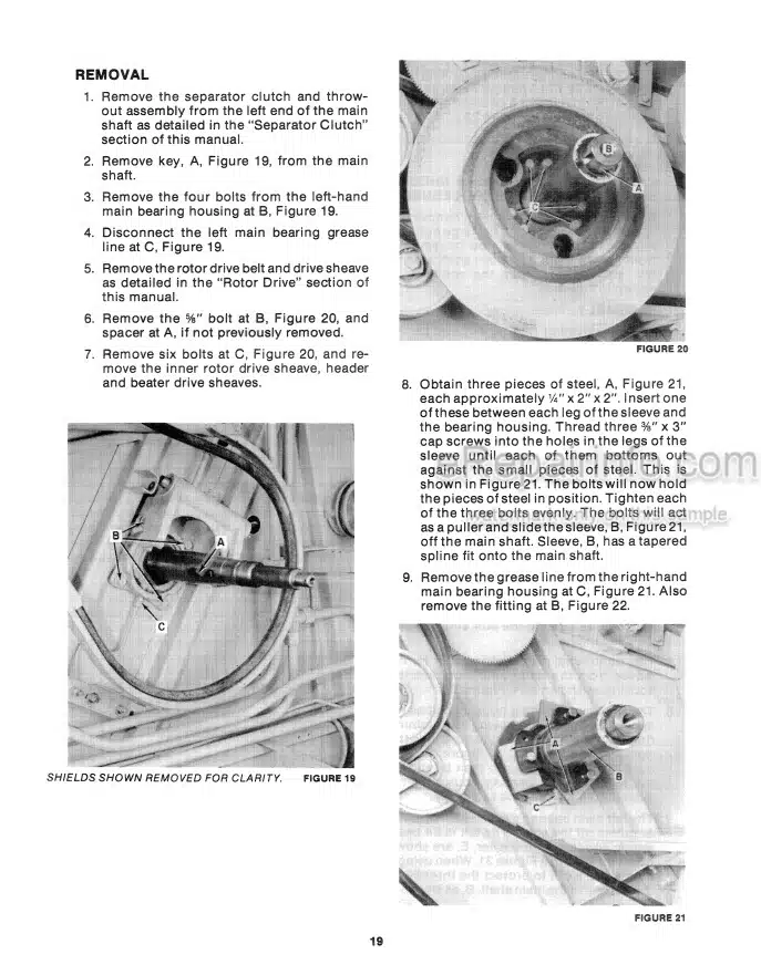
Removal
-POWERED REAR AXLE
Flow Limiters
Flow Limiter Operation
Labor Guide
Motor Assembly
Motor Disassembly
Motor Parts
Motor Parts Inspection
Motor Repair Procedures
Other Information
Powered Rear Axle Control Valve Operation
Powered Rear Axle Motor Operation
Safety
System Function
Troubleshooting
-ROTOR DRIVE
Assembly
Introduction
Labor Guide
Removal Of Lower Variator Sheaves
Rotor Drive – Torque Sensing Drive
Rotor Drive Vari-Speed Motor And Speed Screw
Rotor Drive Vari-Speed Motor And Speed Screw Parts
Servicing
Specifications
Spring Compression Tool
-ROTOR GEARBOXES
Converting Chart
Inspection
Labor Guide
Left-Hand Gearbox Parts List – Style I
Left-Hand Input Shaft Assembly
Left-Hand Input Shaft Disassembly
Left-Hand Rotor Gearbox
Parts Layout
Removing Gearboxes
Right And Left-Hand Output Shaft Assembly Style I
Right And Left-Hand Output Shaft Disassembly Style I
Right Hand Gearbox Parts List Style I
Right Input Shaft Assembly Style I
Right Hand Input Shaft Disassembly Style I
Right Hand Rotor Gearbox
Rotor Gearbox Coupler Alignment
Rotor Gearbox Coupler Parts
Rotor Gearbox Installation
Servicing Rotor Gearboxes Style Ii
Servicing The Left Hand Gearbox Style I
Servicing The Right Hand Gearbox Style
Shim Chart
Shim Use Chart
-ROTORS
Assembly
Balancing
Disassembly
Inspection
Installation
Introduction
Labor Guide
Rasp Bar Shimming
Removal Of Rotors
Rotor Component Alignment
Rotor Timing
-SEPARATOR CLUTCH
Adjustment
Assembly
Disassembly
Inspection
Introduction
Labor Guide
Parts List
-Separator Grates
Installation
Introduction
Labor Guide
Removal
-SPECIFICATIONS
Base Unit
Caterpillar Diesel Engine
Feeder
Ford Diesel Engine
Hydrostatic Drive
Standard Traction Drive
Table Of Speeds
-STANDARD TRACTION DRIVE
Labor Guide
Vari Intermediate Sheave Disassembly
Torque And Conversion Charts ,
Conversion Table (Inches To Millimeters)
Conversion Table (Millimeters To Inches)
-TRACTION CLUTCH SYSTEM
Assembly – Style I
Assembly – Style II
Clutch Parts – Style I
Clutch Parts – Style II
Clutch Specifications Styles I And II
Disassembly – Style I
Disassembly – Style II
Installation
Installation – Style I
Inspection
Inspection Style I And II Clutch
Introduction
Labor Guide
Removal – Style I Clutch
Removal – Style II Clutch
What you get
You will receive PDF file with high-quality manual on your email immediately after the payment.


Reviews
There are no reviews yet.