


Factory Service Manual For Tigercat Forwarder. Manual Contains Illustrations, Instructions, Diagrams For Step By Step Remove And Install, Assembly And Disassembly, Service, Inspection, Repair, Troubleshooting, Tune-Ups.
Format: PDF
Language: English
Pages: 496
Number: 32429A (july 2017)
Bookmarks
Searchable
Wiring Diagrams
Hydraulic Diagrams
Model
Tigercat Forwarder
1055B
1075B
1085B
Serial Number 10550301 To 10551000
Serial Number 10750301 To 10751000
Serial Number 10850101 To 10850500
Contents
INTRODUCTION
MACHINE IDENTIFICATION
SAE STANDARDS
NON-APPROVED FIELD PRODUCT CHANGES
REGULATORY INFORMATION
-SAFETY
Articulation Lock
Battery Disconnect Switch
Battery Safety
Cab Exits
Cab Tilt Support
Cooling System
Emergency Cab Exits
Engine Hood
Exhaust Fumes
Fire Prevention
First Aid
Fluid Injection Injury
Fluid Leaks
Grease Injection Injury
Hydraulic Pressure Hazard
Lightning Safety Awareness
Loose Clothing Hazard
Noise Level Inside Cab
Parking The Machine
Protective Clothing
Releasing Pilot Pressure From The Accumulator
Safety Interlock Switches On Doors
Safety Labels
Safety Precautions, General
Safety Precautions, Operating
Safety Precautions, Servicing
Safety Symbols
Signal Words
Tigercat Crane Safety Precautions
Vibration Levels Inside Cab
Welding, Prior To
Working With Oil
-LUBRICATION AND MAINTENANCE
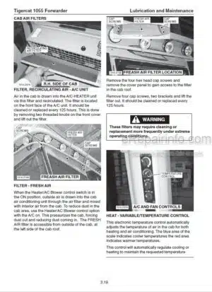
Air Cleaner
Air Conditioning
Air Recirculation Filters
Approved Hydraulic Oils
Axle
Belt – Engine Serpentine (Cummins Engine)
Belt – Engine Serpentine (Mercedes Engine)
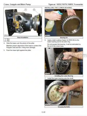
Bogie Housing
Bogie Slew Bearing
Cab
Care Of The Machine
Centre Joint
Charge Pressure Filter-Drive Pump
Control Pod On Armrest, RH
Crane
Crane, Rotator And Grapple Maintenance
Differential
Emergency Exits, Check Monthly
Engine
Engine Serpentine Belt
Filters
Fire Prevention
Fluid Analysis Program
Fluid Sample Collection Procedures
Fresh Air Filter
General Maintenance
Hood
Hydraulic Oils
Initial Pre-Delivery Inspection
Lubrication
Lubrication And Service Points Chart
New Machine Maintenance
Oil Lost From Leakage
Pressure And Speed Settings
Preventive Maintenance Schedule
Scheduled Maintenance
Service And Lubrication Points Chart
Snubber
Startup Procedure After Major Machine Maintenance
Tigercat Crane
Tilting The Cab
Tire Pressures
Torque Chart Machine
Torque Chart Tigercat Grapple
Torque, Fluid Connections
Torque Specifications – General
Unloader Valve
Weights Of Commercial Wood
-ELECTRICAL AND COMPUTERS
Brake Foot Pedal
Cab Fuse And Relay Panel
Channels
Computer
Computer System Components
Connect To The Md3 With IQAN Run 2
Diagnostic Breakout Harnesses
Downloading Applications From Dealer Website
Drive And Brake Foot Pedals
Electrical Kit – Service And Diagnostics
Electrical System Schematic Wiring Diagrams
Engine Fuse And Relay Panel
Fuse And Relay Panels
Holding Brake
Id-Tag
Input And Output Channels
IQAN Modules
IQANRUN 2
IQAN Software
Joystick Control Output Adjustment Settings
Servicing The Md3 With IQANRUN 2
System Components
Troubleshooting Diagnostic Breakout Harnesses
Troubleshooting No Contact Errors
Update Application
Wire Color Code Chart
Worklights Fuse And Relay Panel
-ENGINE AND ANTI-STALL
ADM2 Adaptation Module
Circuit Description
Engine Control Modules
Engine Electronic Controls Locations
Engine Start Circuit
Engine Start Circuit Schematic – 1055B/1075B
Engine Start Circuit Schematic – 1085B
Flex Drive Coupling
Mercedes Engine
PLD-MR Engine Control Module
-DRIVE
All Wheel Drive Switch 1055Band 1075B
Axles
Cab Controls
Circuit Diagram
Circuit Hydraulic Schematic
Drive Electronic Set-Up
Drive Foot Pedal
Drive Motor And Transmission 1055Band 1075B
Drive Motor And Transmission 1085B
Drive Motor Maximum Displacement Setup 1055B
Drive Motor Schematic
Drive Pump
Drive Pump Controller Solenoids
Drive Pump Electronic Set-Up
Drive Pump Pressure Set-Up
Drive Pump Schematic
Gear Selection Switch 1055B And 1075B
Gear Select Manifold
Hydraulic Oil Heating
Hydrostatic Drive Motor
Hydrostatic Drive System
Main Pump
Pump Begin Of Regulation (Min) And Max Displacement
Transmission
Transmission And Drive Motor 1055B And 1075B
Wheel Installation
-BRAKES AND DIFFERENTIAL LOCKS
Accumulator
Brake
Brake Cylinder Stroke Adjustment
Brake Foot Pedal
Brake Inspection 1055B And 1075B
Brake Inspection 1085B
Brake Manifold
Brake Release
Checking Brake Cylinder Stroke 1055B And 1075B
Checking The Coil Current VS Brake Pressure
Circuit Description
Circuit Diagram
Circuit Schematic ~ Brake Valve And High Pressure Manifolds
Differential Locks
Differential Locks Operational Test
Emergency Brakes
High Pressure Manifold
Load Sensing
Low Pressure Brake Manifold
Main Pump
Parking Brake Switch
Service Brake Pressure Setup
Service/Parking Brakes 1055B And 1075B
Service/Parking Brakes 1085B
Setup High Pressure Manifold And Low Pressure Brake Manifold
Tuning The Service Brakes
-COOLING SYSTEM AND FAN
Charge Air Cooler
Circuit Description
Circuit Diagram
Circuit Hydraulic Schematic
Cooling Pump
Engine Serpentine Belt Replacement
Fan Drive
Fan Drive Motor
Fan Manifold
Hydraulic
Oil Cooler/ Radiator/ Charge Air Cooler/ A-C Condenser
Return Strainer
-STEERING, CENTRE JOINT AND OSCILLATION LOCK
Centre Joint
Control Valve (Steer, Gate, Blade)
Hydraulic Valve Compartment – Rear Chassis
Load Sensing
Oscillation Lock Circuit Set-Up
Oscillation Lock Manifold
Oscillation Lock Switch
Steering And Oscillation Lock
Steering, Secondary Controls
Steer Joystick
-CRANE, GRAPPLE AND MAIN PUMP
Boom Valve
Circuit Diagram
Crane
Grapple, Tigercat
Hydraulic System Description
Hydraulic Valve Compartment – Rear Chassis
Load Sensing
Main Pump
Main Pump / Load Sense Set-Up
-SNOW BLADE
Cab Controls
Circuit Description
Circuit Diagram
Circuit Schematic – Blade
Control Valve (Steer, Gate, Blade)
Load Sensing
-GATE
Cab Controls
Circuit Description
Circuit Diagram
Circuit Schematic – Gate
Control Valve (Steer, Gate, Blade)
Control Valve (Steer, Gate, Blade)
Load Sensing
-MISCELLANEOUS
Fire Suppression System – Amerex
Fire Suppression System – Dafo
Ladder Operation
Window Replacement
1055B 1075B 1085B WIRING DIAGRAMS 41750BR15pdf
What you get
You will receive PDF file with high-quality manual on your email immediately after the payment.


Reviews
There are no reviews yet.