


Factory Service Manual For Tigercat Loader. Manual Contains Illustrations, Instructions, Diagrams For Step By Step Remove And Install, Assembly And Disassembly, Service, Inspection, Repair, Troubleshooting, Tune-Ups.
Format: PDF
Language: English
Pages: 144
Number: 30288A (march 2009)
Bookmarks
Searchable
Wiring Diagrams
Hydraulic Diagrams
Model
Tigercat Loader
230C
Contents
INTRODUCTION
NON-APPROVED FIELD PRODUCT CHANGES
-SAFETY
Battery Disconnect Switch
Cooling System
Exhaust Fumes
Fire Prevention
First Aid
Fluid Injection Injury
Fluid Leaks
Grease Injection Injury
Lightning Safety Awareness
Loose Clothing Hazard
Protective Clothing
Safe Removal Of Counterbalance And Check Cartridge
Safety Precautions, Operating
Safety Precautions, Servicing
Safety Symbols
Signal Words
-LUBRICATION & MAINTENANCE
Air Cleaner
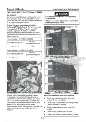
Air Conditioning
Approved Hydraulic Oils
Electrical Schematic
Filter Restriction Indicator
Fire Prevention
First 50-100 Hour Inspection And Service
Hydraulic Oil Return Filters
Lubrication And Service Points
New Machine Maintenance
Oil Lost From Leakage
Oil Sample Collection Procedures
Oil Sampling Program
PAG Oil
Pilot Pressure Filter
Pre-Delivery Inspection
Pressure Settings
Preventive Maintenance Schedule
Refrigerant
Scheduled Maintenance
Torque Chart
Torque, Fluid Connections
Torque Specifications – General
Unloader Valve
Weights Of Commercial Wood
-PILOT SYSTEM
Circuit Diagram
Electrical Circuit
Pilot Circuit Components
Pilot System Components
Pressure Settings
-ELECTRICAL, GAUGES & ALARMS
Cab Wiring And Electrical Component Locations
Display Module
Electrical Schematic
Front Instrument Panel – Wiring Diagram
Fuse And Relay Panel – Cab
Fuses And Relays – Electrical Box
Gauges And Alarms
Instrument Panel Wiring Diagram
Sensor Locations
Warning Lights
Wire Colour Code Chart
-ENGINE START AND STOP
Circuit Description
Engine Start Circuit
Start Circuit Diagrams
-OIL COOLER, RADIATOR AND FAN
Check Engine Coolant Level
Cooling System
Oil Cooler Circuit Description
Oil Cooler Circuit Diagram
Oil Cooler. Radiator And Fan
-BOOM
Circuit Description
Circuit Diagram
Control Valves
Filters
Hoist Valve Relief Valve Settings
Stick Valve Relief Valve Settings
-SWING
Circuit Description
Circuit Diagram
Control Valves
Gearbox, Swing Drive
Pressure Settings
Swing Bearing
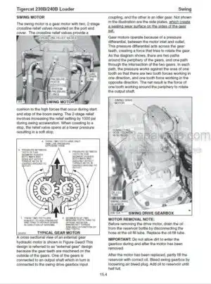
Swing Motor
Swing Pump
-STABILIZERS
Circuit Diagram
Lower Frame Hydraulic Connections
Pilot Manifold
Pressure Settings
Safe Removal Of Counterbalance And Check Cartridge
Stabilizer Circuit Description
Stabilizer Control Valve
Stabilizer Cylinders And Counterbalance Valves
Stabilizer Pilot Manifold
-GRAPPLE
Circuit Description
Circuit Diagram
Grapple Connections To Boom
Grapple Control Valves
Grapple Pump
Joystick Control Valve
Pressure Settings
-DELIMBER/SLASHER
Circuit Description
Circuit Diagram
Control Valves
Delimber/Slasher Circuit Description
Delimber/Slasher Connections
Delimber/Slasher Pump
Electrical Circuit
Hydraulic Circuit Lower Frame
Main Hydraulic Circuit Upper Frame
Pilot Circuit Components
Pilot Manifold
Pressure Settings
Trouble Shooting Delimber Relay Circuit
What you get
You will receive PDF file with high-quality manual on your email immediately after the payment.


Reviews
There are no reviews yet.