


Factory Service Manual For Tigercat Loader. Manual Contains Illustrations, Instructions, Diagrams For Step By Step Remove And Install, Assembly And Disassembly, Service, Inspection, Repair, Troubleshooting, Tune-Ups.
Format: PDF
Language: English
Pages: 424
Number: 35177A (july 2015)
Bookmarks
Searchable
Wiring Diagrams
Hydraulic Diagrams
Model
Tigercat Loader
234
Serial Number 2340601 To 2342000
Contents
INTRODUCTION
NON-APPROVED FIELD PRODUCT CHANGES
-SAFETY
Articulation Lock
Battery Disconnect Switch
Battery Safety
Cab Exits
Cooling System
Emergency Cab Exits
Engine Doors
Exhaust Fumes
Fire Prevention
Fluid Injection Injury
Fluid Leaks
Grease Injection Injury
Hydraulic Pressure Hazard
Lightning Safety Awareness
Loose Clothing Hazard
Parking The Machine
Protective Clothing
Safe Removal Of Counterbalance And Check Cartridge
Safety Interlock Switch
Safety Labels
Safety Precautions, General
Safety Precautions, Operating
Safety Precautions, Servicing
Safety Symbols
Signal Words
Welding, Prior To
Working With Oil
-LUBRICATION AND MAINTENANCE
Air Cleaner
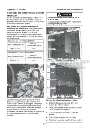
Air Conditioning
Air Filter
Air Filter Restriction Indicator
Approved Hydraulic Oils
Case Drain Strainer, Hydraulic Oil
Emergency Cab Exits
Filters
Fire Prevention
First 125 Hour Inspection And Service
Fuel Filter And Fuel Filter/Water Separator
Fuel – Refueling Procedure
Fuel Tank
Hand Fill Pump, Hydraulic Oil
Hydraulic Oil
Hydraulic Tank Vacuum System
Lubrication And Service Points
New Machine Maintenance
Oil Lost From Leakage
Oil Sample Collection Procedures
Oil Sampling Program
PAG Oil
Pre-Delivery Inspection
Pressure Settings
Preventive Maintenance Schedule
Refrigerant
Refueling Procedure
Rotary Manifold Lubrication
Scheduled Maintenance
Service And Lubrication Points
Strainer, Case Drain
Swing Drive Lubrication
Torque Chart
Torque, Fluid Connections
Torque Specifications – General
Unloader Valve
Vacuum System, Hydraulic Tank
Weights Of Commercial Wood
-HYDRAULIC SYSTEM
Circuit Diagram
Electronic Controls Description
Hydraulic Oil Reservoir
Hydraulic Pumps
Hydraulic System Operation
Load Sensing
Main Control Valve
Main Pump POR Valve Setting
POR Valve Setting
-PILOT SYSTEM
Pilot Control System Circuit Diagram
Pilot Hydraulic Schematic
Pilot Shut-Off Circuit Diagram
Pilot System Components
Pressure Settings
-ELECTRICAL SYSTEM AND COMPUTER
Alternator
Battery Compartment
Battery Disconnect – Switch
Cold Weather Starting
Computer
Electrical Schematics
Electrical System
Fuses And Relays – Cab
Fuses And Relays – Rear Panel
Gauges and Alarms
Low Fuel Level – Flashing Icon
Md3 Computer
Md3 Computer Main Menu
Screen Saver Adjustment
Sensors And Electrical Component Locations
Wait To Start
-ENGINE AND ANTI-STALL
Adjustment Menu
Anti-Stall System Components
Circuit Description
Computer
Electrical Schematic – Engine Management
Emergency Stop Circuit
Emergency Stop Switch
Engine Start Circuit
Fault Finding Procedure, Anti-Stall Quick Check
Fault Finding Procedures, Additional
Selecting Anti Stall Mode
-RADIATOR, OIL & CHARGE AIR COOLER
Charge Air Cooler
Compartment Access, Engine
Cooling System
Engine Belts
Oil Cooler
Radiator, Oil Cooler And Charge Air Cooler
-BOOM
Boom Circuit Description
Boom System Components
Boom Valve Spool Sections
Circuit Diagrams
Electronic Adjustment Procedure
Electronic Settings Description
Hoist Valve Relief Valve Settings
Machine Mode
Pressure Settings
Pressure Settings, Port Relief Valves
Stick Valve Relief Valve Settings
-SWING
Circuit Diagram
Gearbox, Swing Drive
Hydrostatic Drive Motor
Pressure Settings
Swing Bearing
Swing Motor
Swing Pump
-STABILIZERS
Circuit Components
Circuit Description, Stabilizer
Control Valve
Counterbalance And Check Cartridges, Removal
Counterbalance Valves
Cylinders And Counterbalance Valves
Electrical Circuit Schematic, Stabilizer
Hydraulic Circuit Schematic, Stabilizer
Lowering Stabilizer
Pressure Settings
Raising Stabilizer
-GRAPPLE
Circuit Description
Circuit Diagrams
Electronic Adjustment Procedure
Electronic Settings Description
Grapple Connections To Boom
Grapple Control Valves
Grapple System Components
Machine Mode
Pressure Settings
Pressure Settings, Port Relief Valves
-DELIMBER/SLASHER
Circuit Description
Circuit Diagrams
Control Valve Delimber
Control Valve Saws Retract Slasher Cut
Delimber/Slasher Circuit Components
Delimber/Slasher Connections
Delimber/Slasher Electrical
Delimber/Slasher Pump
Electronic Adjustment Procedure
Machine Mode
Pressure Settings
What you get
You will receive PDF file with high-quality manual on your email immediately after the payment.


Reviews
There are no reviews yet.