


Factory Service Manual For Tigercat Cable Skidder. Manual Contains Illustrations, Instructions, Diagrams For Step By Step Remove And Install, Assembly And Disassembly, Service, Inspection, Repair, Troubleshooting, Tune-Ups.
Format: PDF
Language: English
Pages: 368
Number: 26695A (december 2010)
Bookmarks
Searchable
Wiring Diagrams
Hydraulic Diagrams
Model
Tigercat Cable Skidder
604
604C
Contents
INTRODUCTION
S.A.E. STANDARDS
NON-APPROVED FIELD PRODUCT CHANGES
-SAFETY
Battery Disconnect Switch
Battery Safety
Cab Exits
Cab Safety Cable
Cab Support Brace
Cooling System
Emergency Cab Exits
Exhaust Fumes
Fire Prevention
First Aid
Fluid Injection Injury
Fluid Leaks
Grease Injection Injury
Hydraulic Pressure Hazard
Loose Clothing Hazard
Parking The Machine
Protective Clothing
Safety Precautions, General
Safety Precautions, Operating
Safety Precautions, Servicing
Safety Symbols
Signal Words
Welding. Prior To
Working With Oil
-LUBRICATION & MAINTENANCE
Air Cleaner Maintenance
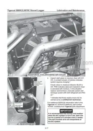
Air Conditioning System, Checking
Approved Hydraulic Oils
Articulation Lock
Axle Level Check, Fill
Cab Safety Cable
Cab Support Brace
Center Joint
Emergency Exits, Check Monthly
Engine Air Cleaner
Filters
Fire Prevention
General Maintenance
Hour Meter ~ Maintenance
Lubrication And Service Points
New Machine Maintenance
Oil Lost From Leakage
Oil Sample Collection Procedures
Oil Sampling Program
Pressurized Water System Maintenance
Scheduled Maintenance
Service And Lubrication Points
Startup Procedure After
Tilting The Cab
Torque Chart
Torque, Fluid Connections
Torque Specifications – General
Weights Of Commercial Wood
Wheels, Installing
Winch Maintenance – Allied Only
-ELECTRICAL AND COMPUTERS
Alarms And Gauges
Channels
Computer
Computer System Overview
Current Out – Troubleshooting For Open Circuits
Downloading Applications From Dealer Website
Electrical Kit – Service And Diagnostics
Electrical System Schematic Diagrams
Error Messages And Alarms
Fault Codes : Error Messages
Fault Codes, Reading Active Engine Codes
Fuse And Relay Panels
Gauges And Alarms
Get Application
Get Error/Event Log
ID-Tag
Information Center -IQAN MDM Computer Display
IQAN Modules
IQAN Software
Main System Errors
Module Is Offline
PDA Registration
Reading Engine Fault Codes
Switch And Sensor Locations
Update Application
Wire Colour Code Chart
-ENGINE START AND STOP
Start Circuit Description
Start Circuit Diagram
-DRIVE
Axles
Cab Support Brace
Circuit Description
Circuit Diagram
Circuit Hydraulic Schematic
Drive Motor
Drive Motor Speed Verification
Drive Pump
Drive Pump Pressure Checks
Hydraulic Oil Heating Procedure
Hydrostatic Setup Procedure
Maximum Speed Control Dial
Special Tools For Wheel End Assembly
Startup Procedure After Major Maintenance. See Section 3
Transmission
Travel/Engine Speed Pedals
-BRAKES AND DIFFERENTIAL LOCKS
Accumulator
Charging Valve, Accumulator
Circuit Description
Circuit Diagram
Circuit Hydraulic Schematic
Control Valve
Control Valve Electrical Schematic
Load Sensing
Main Pump
Multifunction Manifold
Parking Brake – Hydraulic
Pressure Checks
Pressure Settings, Main Pump
Priority Valve. See Section 11
Service Brakes
-OIL COOLER
Circuit Description
Circuit Diagram
Circuit Hydraulic Schematic
Cooling Pump
Filter, Hydraulic Double Element
Flow Control Valve
Hydraulic Oil Tank, Main
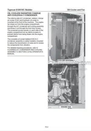
Oil Cooler/ Radiator/ Charge Air Cooler
Suction Strainer
Variable Pitch Fan (Optional – 6040201 And Up)
-STEERING AND CENTER JOINT
Center Joint
Priority Valve
Steer Control Valve
Steering
Testing The Steering Operation
-WINCH
Allied Winch
Control Valve
Control Valve Characteristics
Control Valve Electrical Schematic
Multifunction Manifold
Pressure Checks
Winch Control Lever
-DOZER BLADE
Circuit Description
Circuit Diagram
Control Valve
Control Valve Electrical Schematic
Dozer Control Lever
Hydraulic Schematic. Circuit
Pressure Checks
What you get
You will receive PDF file with high-quality manual on your email immediately after the payment.


Reviews
There are no reviews yet.