


Factory Service Manual For Tigercat Skidder. Manual Contains Illustrations, Instructions, Diagrams For Step By Step Remove And Install, Assembly And Disassembly, Service, Inspection, Repair, Troubleshooting, Tune-Ups.
Format: PDF
Language: English
Pages: 236
Number: 11583A (ocotber 2003)
Bookmarks
Searchable
Wiring Diagrams
Hydraulic Diagrams
Model
Tigercat Skidder
620
Contents
INTRODUCTION
S.A.E. STANDARDS
NON-APPROVED FIELD PRODUCT CHANGES
-SAFETY
Articulation Lock
Battery Disconnect Switch
Cab Safety Cable
Cab Support Brace
Cooling System
Exhaust Fumes
Fire Prevention
First Aid
Fluid Leaks
Hydraulic Pressure Hazard
Loose Clothing Hazard
Parking The Machine
Protective Clothing
Safety Precautions, General
Safety Precautions, Operating
Safety Precautions, Servicing
Safety Symbols
Signal Words
-LUBRICATION & MAINTENANCE
Air Cleaner Maintenance
Approved Hydraulic Oils
Center Joint
Charge Pressure Filter
Filter And Lubrication Schedule
Filters
Fire Prevention
General Maintenance
Grapple Snubber Maintenance
Hour Meter ~ Maintenance
Lubrication And Service Points
New Machine Maintenance
Oil Lost From Leakage
Pressurized Water System Maintenance
Scheduled Maintenance
Service And Lubrication Points
Speed Control Lever Adjustment
Startup Procedure After Major Maintenance
Tilting The Cab
Torque Chart
Torque Chart, General
Wheels, Installing
Winch Lubrication – Lantec Only
Winch Lubrication – Lufkin Only
-PILOT SYSTEM
Charge Pressure Filter
Charge Pump
Circuit Description
Circuit Diagram
Pilot Manifold
Pressure Settings
-ELECTRICAL, GAUGES AND ALARMS
Fuse And Relay Panel
Gauges And Alarms
Schematic Diagram
Sensor Details
Switch And Sensor Locations
Troubleshooting And Testing
Wire Colour Code Chart
-ENGINE START AND STOP
Drive Prevent Valve
Fuel Control Valve
Main Pump Unloading Valve
Start Circuit Description
Start Circuit Diagram
Start Motor And Solenoid
Start Solenoid Relay
Tachometer Set-Up
-DRIVE
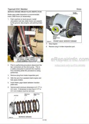
Axles
Circuit Description
Drive System
Hydraulic Oil Heating Procedure
Test Drive – Rexroth Pump And Rexroth Motors
Test Drive – Sauer Pump And Rexroth Motors
Transmission
Transmission Identification
Wheel Installation
-BRAKES
Accumulator
Brakes
Charging Valve, Accumulator
Circuit Diagram
Differential Locks
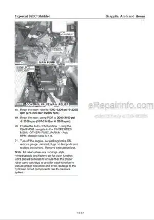
Main Pump
Multifunction Valve
Parking Brake
-OIL COOLER/RADIATOR AND FLEXXAIRE FAN
Circuit Description And Operation
Circuit Diagram
Flexxaire Fan Maintenance (Optional Item)
Oil Cooler/Radiator Description
Radiator/Oil Cooler Description
-STEERING AND CENTER JOINT
Center Joint
Identifying Earlier And Later Bearings
Priority Valve
Steer Control Valve
Steering
Testing The Steering Operation
-GRAPPLE, ARCH AND BOOM
Circuit Description
Circuit Diagrams
Grapple Control Valve
Grapple Snubber Maintenance See Section 3
Joystick Control Valve, Arch And Grapple
Port Relief Valve Description (Grapple Valve)
Pressure Settings
Relief Valves
Snubber Maintenance – Grapple See Section 3
-WINCH
Control Lever Valve
Grapple Control Valve
Lantec Winch
Lufkin Winch
Pressure Settings
-DOZER BLADE
Circuit Description
Circuit Diagram
Control Lever Pilot Valve
Dozer Control Valve
Pressure Settings
What you get
You will receive PDF file with high-quality manual on your email immediately after the payment.


Reviews
There are no reviews yet.