


Factory Service Manual For Tigercat Skidder. Manual Contains Illustrations, Instructions, Diagrams For Step By Step Remove And Install, Assembly And Disassembly, Service, Inspection, Repair, Troubleshooting, Tune-Ups.
Format: PDF
Language: English
Pages: 210
Number: 6701A (march 2003)
Bookmarks
Searchable
Wiring Diagrams
Hydraulic Diagrams
Model
Tigercat Skidder
630
Contents
INTRODUCTION
S.A.E. STANDARDS
NON-APPROVED FIELD PRODUCT CHANGES
-SAFETY
Battery Disconnect Switch
Cooling System
Exhaust Fumes
Fire Prevention
First Aid
Fluid Leaks
Hydraulic Pressure Hazard
Loose Clothing Hazard
Protective Clothing
Safety Precautions, General
Safety Precautions, Operating
Safety Precautions, Servicing
Safety Symbols
Signal Words
-LUBRICATION & MAINTENANCE
Center Joint
Filter And Lubrication Schedule
Filters – Remove And Replace
Fuel Tank Strainer
General Maintenance
Grapple Snubber Maintenance
Hour Meter ~ Maintenance
New Machine Maintenance
Oil Lost From Leakage
Pressure Settings
Scheduled Maintenance
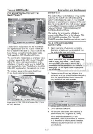
Servicing Air Conditioning System
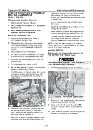
Startup Procedure After Major Maintenance
Tightening Points
Torque Chart
Torque Chart, General
Wheels, Installing
Winch Lubrication
-PILOT SYSTEM
Charge Pressure Filter
Charge Pump
Circuit Diagram Serial Number
Pilot Manifold
Pilot Oil Circuit
Set Pilot Pressure
-ELECTRICAL, GAUGES AND ALARMS
Fuse And Relay Panel
Gauges And Alarms
Schematic Diagram
Sensor Details
Switch And Sensor Locations
Troubleshooting And Testing
Wire Colour Code Chart
-ENGINE START AND STOP
Circuit Description
Circuit Diagram
Drive System Relays
Engine Start Circuit
Fuel Control Valve
Main Pump Unloading Valve
Parking Brake Switch
Start Motor And Solenoid
Start Solenoid Relay
Tachometer Set-Up
-DRIVE
Axles
Drive System
Hydraulic Oil Heating Procedure
Test Drive
Transmission
Wheel Installation
-BRAKES
Accumulator
Brakes
Charging Valve, Accumulator
Circuit Diagram
Differential Locks
Multifunction Valve
Parking Brake
-OIL COOLER
Circuit Description And Operation
Circuit Diagram
Oil Cooler Description
-STEERING AND CENTER JOINT
Center Joint
Circuit Diagram
Priority Valve
Steer Control Valve
Testing The Steering Operation
-GRAPPLE, ARCH AND BOOM
Circuit Description
Circuit Diagrams
Grapple Control Valve
Grapple Snubber Maintenance
Joystick Control Valve, Arch And Grapple
Port Relief Valve Description (Grapple Valve)
Pressure Settings
-WINCH
Circuit Description
Circuit Diagrams
Control Lever Valve
Grapple Control Valve
Pressure Settings
-DOZER BLADE
Circuit Description
Circuit Diagrams
Control Lever Pilot Valve
Dozer Control Valve
Pressure Settings
-LOW POWER COMPLAINT CHECKLIST
Engine Stall Test
Check Main Pump Relief And P.O.R.
Check Air Cleaner
Check Fuel Filter/ Water Separator
Drive Test
Check Air Intake Manifold
Check Fuel Shut-Off Solenoid
Check Air Hoses
Check Diaphragm In The Injection Pump
Check Waste Gate Actuator For Leaks
Check Waste Gate Actuator For Travel
Check Injector Pump Timing
Check For Misfiring Cylinders
Check Injector Spray Pattern
Check Engine Blow-By
Trouble Shooting Guide
What you get
You will receive PDF file with high-quality manual on your email immediately after the payment.


Reviews
There are no reviews yet.