Factory Service And Maintenance Manual For Tigercat Feller Buncher. Manual Contains Illustrations, Instructions, Diagrams For Step By Step Remove And Install, Assembly And Disassembly, Service, Inspection, Repair, Troubleshooting, Tune-Ups.
Format: PDF
Language: English
Pages: 256
Number: 30851A (july 2015)
Bookmarks
Searchable
Wiring Diagrams
Hydraulic Diagrams
Model
Tigercat Feller Buncher
718E
Serial Number 7180901 To 7182000
Contents
INTRODUCTION
NON-APPROVED FIELD PRODUCT CHANGES
-SAFETY
Access Panels
Backover Accidents
Battery Safety
Boom Lift Lock
Felling Trees
Fire Prevention
Fluid Injection Injury
Grease Injection Injury
Lightning Safety Awareness
Parking The Machine
Safety Hazards – Operating
Safety Hazards – Viton Seals
Safety Interlock Switches On Cab Doors
Safety Labels
Safety Precautions, General
Safety Precautions, Operating
Safety Precautions, Servicing
Safety Symbols
Signal Words
Working With Oil
-LUBRICATION AND MAINTENANCE
Scheduled Maintenance
Air Cleaner Maintenance
Air Conditioning System Checking
Belt, Engine Serpentine, Replacing
Blink Codes
Center Joint
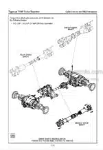
Drive Shaft Spline Lubrication, Middle And Rear
Filters
Fire Prevention
Hydraulic Oils
New Machine Maintenance
Oil Lost From Leakage
Oil Sample Collection Procedures
Oil Sampling Program
Pressure Settings – Saw
Pressure Settings – Shear
Pressurized Water System Maintenance
Priming The Fuel System
Pump Drive Gearbox Oil Level
Service And Lubrication Points Chart
Speed Control Lever Adjustment
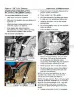
Startup Procedure After Maintenance
Torque Chart, General
Torque, Fluid Connections
Transmission – Check Oil Level
Weights Of Commercial Wood
Wheels, Installing
-PILOT SYSTEM
Accumulator
Accumulator Charge Valve
Accumulators
Components
Hydraulic Oil Heating Procedure
Main Relief Valve Pressure Setting
Pilot Circuit Description
Pilot Circuit Schematic
Pilot Manifold
Pilot Pressure Settings
Pilot System Components
Release Pilot System Pressure
Troubleshooting Guide
Unloading Valve Pressure Setting
-ELECTRICAL, GAUGES AND ALARMS
Blink Codes
Blink Code Translation / Diagnostics
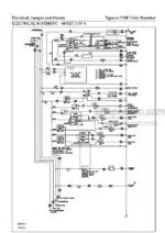
Electrical Schematics
Fuse And Relay Panel – Cab
Fuse And Relay Panel – Main
Relays And Wire Connections
Sensor, Sender Locations
Wire Color Code Chart
Wire Connections – Relays
-ENGINE
Charge Air Cooler
Circuit Description
Cooling System
Precleaner
Start Circuit Diagrams
Starting System Description
-DRIVE
Axles
Circuit Description
Circuit Diagram, Drive
Drive Motor Pressure Settings And Adjustments
Drive Pedal Pilot Valve
Drive Prevent Valve
Drive Pump Pressure Settings And Adjustments
Drive Shaft, Front, Installation
Hydrostatic Drive Motor Description
Hydrostatic Drive System-Single Motor 2-Speed Transmission
Parking Brake Operation
Pressure Setting Chart
Pressure Settings And Adjustments
Test Drive
Transmission 2-Speed (Single Motor)
Wheel Installation
-BRAKES AND DIFFERENTIAL LOCKS
Brakes
Differential Locks
Parking Brake – Hydraulic
-COOLING SYSTEM
Charge Air Cooler
Cleaning
Flexxaire Fan Maintenance (Optional Item)
Oil Cooler
Oil Cooler Operation
-STEERING AND CENTRE JOINT
Center Joint
Joystick Control Valve
Pilot Manifold
Pressure Setting Chart See Section 3 – Lubrication And Maintenance
Pressure Settings
Safety
Steer/Boom Pump
Steer Circuit
Steer Valve
-LIFT BOOM
Boom Lift Lock
Boom Valve
Circuit Diagram
Joystick Control Valve
Pressure Setting Chart
Pressure Settings
Pump, Description
Relief Valves
-TILT
Boom Lift Lock
Boom Valve
Circuit Description
Circuit Diagram
Control Valves
Pressure Setting Chart
Pressure Settings
Safety
-SAW DRIVE
Circuit Diagram
Motor Begin Of Stroke See Felling Head Manual
Motor Minimum Displacement See Felling Head Manual
Pressure Setting Chart See Section 3 – Lubrication And Maintenance
Saw Control Valve
Saw Electrical Circuit Schematic
Saw Pump
-CLAMPS WITH SAW
Boom Lift Lock
Boom Valve
Circuit Description
Circuit Diagram
Control Valves
Pilot Line Pressures
Pressure Settings
Relief Valves
Safety
Spool Section Diagram
-SHEAR WITH CLAMPS
Boom Lift Lock
Boom Valve
Circuit Description
Circuit Diagram
Control Valves
Foot Operated Pilot Valve
Pressure Settings
Safety
What you get
You will receive PDF file with high-quality manual on your email immediately after the payment.



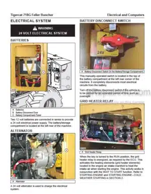
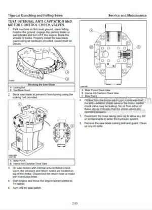
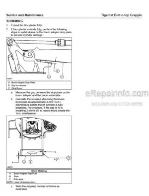
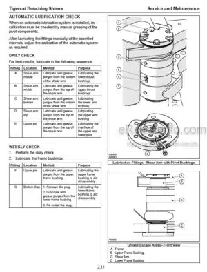
Reviews
There are no reviews yet