


Factory Service Manual For Tigercat Feller Buncher. Manual Contains Illustrations, Instructions, Diagrams For Step By Step Remove And Install, Assembly And Disassembly, Service, Inspection, Repair, Troubleshooting, Tune-Ups.
Format: PDF
Language: English
Pages: 764
Number: 60154AENG (january 2020)
Bookmarks
Searchable
Wiring Diagrams
Hydraulic Diagrams
Model
Tigercat Feller Buncher
870D
L870D
Serial Number 87013501 To 87015000
Serial Number 87023501 To 87025000
Contents
INTRODUCTION
-SAFETY
Avoid Injury From Backover Accidents
Battery Safety
Cab Exits
Cable Assist114
Cooling System
Diesel Exhaust Fluid (DEF)
ER Boom System
ER Boom System Precautions
Felling Trees
Fire Prevention
Fluid Injection Injury
General Safety Precautions
Grease Injection Injury
Hazard Zone
Hydraulic Pressure Hazard
Lightening Safety Awareness
Loose Clothing Hazard
Machine Stability And Traction
Operating Safety Precautions
Parking The Machine
Protective Clothing
Safety Interlock Switches On Cab Doors
Safety Precautions, Servicing
Servicing Safety Precautions
Signal Words
Welding, Prior To
Wet Chemical Cleanup Procedure
Working With Oil
-USING HIGH-SPEED DISC SAWS SAFELY APPENDIX TO SECTION 1
Comments And Instructions
Dangers
Foreword
Housing Types
Saw Head Do Nots
Type Of Housing Makes A Difference
-CONTROLS AND OPERATION
A/C/DEFrost Switch
Air Source Switch
Alarm
Attachment, Instructions And Precautions
Auxiliary Input
Auxiliary Power Outlet, 12 V
Battery Boosting
Battery Disconnect Switch
Belt Routing, Serpentine
Boom Controls
Cab Dome Light Switch
Camera
Cold Weather Starting
Computer
Computer And Display
Computer Display-Home Screen
Computer Display Messages
Critical Messages
Control Panel
Controls
Coolant Shut-Off Valves
Coolant Shut-Off Valves, Engine
Cooling Fan Switch
Current Output Channels
Display, Video
Electronic Device Holder
Emergency Exits
Engine, Restarting After Engine Runs Out Of Fuel
Engine Speed Switch
Engine, Stopping
ER Boom System, Instructions
Fan Service Mode
Fan Speed Switch
Filters
Fire Extinguisher, Cab
Fire Extinguisher, Portable
Fire Suppression System
Fire Suppression System Type A
Fuel, Refuelling Procedure
Fuel Tank
Heat/Cool Temperature Knob
Heater Control Panel Engine Coolant (Optional)
Horn/Safety Alert Switch
Joysticks Controls
Key Switch
Lights
Load Sensing, Operating Tips
Operating The Machine
Operating Tips With Load Sensing
Operation Modes
Operator’s Manual
Operator’s Manual Case
Operator’s Seat
Pictograms
Pilot System Off, Push Button Switch
Pilot System Off Switch
Pilot System Reset Switch
Power Roof Switch
Power Side Door Switch
Radio
Rearview Camera
Refuelling Procedure
Saw Switch
Serpentine Belt Routing
Service Work Light Switch And Indicator Light
Skyview Camera
Slope Indicators
Starting Engine
Storage Area
Swing Brake Switch
Swing Control, Joystick
Switch
System Test And Warm Up
Telematics Repair Mode
Track Drive Controls
Track Range (High/Low) Switch
Travelling, Boom Raised
Travel Speed Control
USB Connection
Video Display, Camera
Warm Up Mode
Work Light Switches
-LUBRICATION AND MAINTENANCE
Adding Engine Coolant
Aftertreatment System
Aftertreatment System (Denox 22 System, Tier 4F)
Air Cleaner Housing
Air Conditioning System
Air Filters
Air Intake System
Anti-Corrosion Spray, Removal, If Applicable
Approved Anti-Seize Pastes For Exhaust/Aftertreatment Sensors
Approved Hydraulic Oils
Battery Box Cover
Battery Care
Care Of Polycarbonate Windows
Care Of The Machine
Check Engine Coolant Level
Cleaning
Cleaning Cooler Package
Clean Out Cover
Clean Out Cover
Commercial Wood-Weights
Cooler Package-Cleaning
DEF (Diesel Exhaust Fluid, Tank
Diagnostics Connection, Engine
Diesel Exhaust Fluid (DEF)
Diesel Exhaust Fluid (DEF) Handling And Storage
Diesel Exhaust Fluid (DEF) Tank
Diffusers
Diffusers/Strainers – Hydraulic Oil Return
Draining Engine Coolant
Draining Hydraulic Oil Tank
Emergency Exit-Maintenance Guide
Emergency Exits, Check Monthly
Enclosure Access Door
Engine Bottom Access Cover
Engine Diagnostics Connection
Engine Oil Drain Plug Access Cover
ER Boom System
Filling The DEF Tank
Filters
Fire Prevention
Fire Suppression System Component Location Type A
Fire Suppression System Component Location Type B
Fluid Analysis Program
Fluid Sampling Program
Fuel Heater
Fuel System
Fuel Tank
Fuel Tank Drain Plug Bottom Access Cover
Fuses And Relays
Graffiti Removal
Hydraulic Adjustments Table
Hydraulic Oil Fill Pump
Hydraulic Oil Level Sight Gauges
Hydraulic Oil Tank
Hydraulic Oil Tank Breather
Hydraulic Oil Tank Pressurization Instructions
Hydraulic Oil Tank Vacuum System (If Equipped)
Hydraulic Pump Compartment Bottom Access Cover
Hydraulic System
Leveler Cylinder Locks
Main Control Valve Bottom Access Cover
New Machine Maintenance
Oil Lost From Leakage
Pilot Filter
Power Roof
Power Side Door
Power Unit
Pressure And Speed Settings
Pressure Washing
Preventive Maintenance Schedule
Pump Case Drain Filter
Pump Cover
Pump Cover Side Door
Rear Door
Refilling The Hydraulic System
Relays And Fuses
Remote Fuel Tank, Coolant Heater Unit (Optional)
Rotary Manifold Seal Lubrication
Scheduled Maintenance
Serpentine Belt, Inspection Replacement
Serpentine Belt Routing
Service And Lubrication Schedule
Service And Maintenance Access Doors And Covers
Service Compartment Bottom Access Cover
Strainers, Case Drain
Swing Drive Gearbox Lubrication
Temperature Sender
Timed Purge Interval
Torque Chart, General
Torque, Fluid Connections
Track
Track Chain
Track Components
Track Drive Gearbox
Track Motor Cover
Track Operation And Wear Prevention
Track Sag Adjustment
Weights Of Commercial Wood
Windows
Wood, Weights Of Commercial Wood
-HYDRAULIC SYSTEM
Case Drain Filter
Hydraulic Fundamentals
Hydraulic Oil Tank
Hydraulic System Overview
Load Sense Relief Pressure Setting
Margin Pressure Setting
Test Main Hydraulic Pump Wear
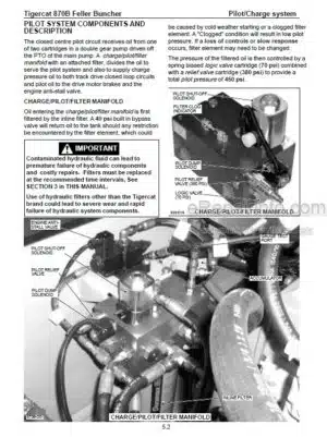
-PILOT SYSTEM
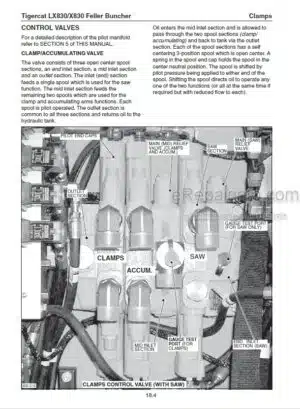
Controls
Hydraulic Circuit Diagram Pilot System
Hydraulic Schematic Pilot System
Pilot Supply Pressure Setting
Pilot System
Pilot System Components
Pilot System Electrical Circuits
-ELECTRICAL AND COMPUTERS
Battery Care
Cab Electrical Installation
Channels
Computer
Computer Modules
Connect To The Computer With IQUANRUN 4
Diagnostic Connector, Engine
Downloading Applications From The Tigercat Dealer Website
Electrical Kit-Service And Diagnostics
Electrical Schematic
Electrical System Overview
Engine Diagnostic Connector
Fuses And Relays
Id-Tag
IQANRUN 4
IQAN Software
Servicing The Computer With IQANRUN 4
Telematics System
Upper Frame Electrical Installation
-ENGINE AND ANTI-STALL
Anti-Stall And Load Sense Electrical Schematic
Engine Anti-Stall System
Engine Diagnostic Connector
Flex Drive Coupling
Load Sensing
Starting And Stopping The Engine
-COOLING SYSTEM
A/C Condenser And A/C System
Charge Air Cooler
Coolant Pre-Heating System (Optional)
Cooling System
Diesel Exhaust Fluid (DEF) Coolant System
Fan Control System
Fan Drive System
Fan Pump Speed
Fan System Testing
Heater System
Hydraulic Oil Cooler Circuit
Radiator
-TRACK DRIVE
Hydraulic Circuit Diagram Track Drive (Upper Structure Components)
Hydraulic Circuit Diagram Type B Track Drive (Undercarriage Components)
Hydraulic Circuit Diagram Type C Track Drive (Undercarriage Components)
Hydraulic Drive Motor Control Valve Sections
Hydraulic Drive System
Hydraulic Schematic, Type B Track Drive
Hydraulic Schematic, Type C Track Drive
Important Track Drive Information
Measure Track Sag
Parking Brake Disc Replacement (Type A)
Parking Brake Disc Replacement (Type B)
Pressure And Speed Settings Type B
Pressure And Speed Settings Type C
Rotary Manifold
Rotary Manifold Seal Installation
Summary Of Track Speed Adjustment Procedure
Torquing Undercarriage Bolts
Track Drive Gearbox Identification
Track Drive Motors
Undercarriage Components
Wear Limits
-BOOM FUNCTIONS
Adjust Flow Cycle Times
ER Boom System Description
ER Boom Valve
ER/Cooler Bypass Valve
Hoist And Stick Control Valve
Hoist And Stick Functions (ER Boom System)
Hydraulic Circuit Diagram
Hydraulic Schematic
Pressure Settings
Tilt Function
-LEVELING
Check Leveling Speed
Circuit Diagram
Counterbalance Valve Pressure Setting
Electrical Schematic
Hydraulic Schematic
Hydraulic Schematic, Leveling System
Leveler Component Lubrication
Leveling Cylinder Counterbalance Valves
Leveling Cylinder Taper Lock Pins
Leveling Electronic Adjustment
Leveling Valve Port Relief Pressure
Side Pivot Axis Bearings
-SWING
Crossline Relief Valve Settings
Hydraulic Circuit Diagram Swing Drive
Hydraulic Schematic, Priority Swing Valve And Plate
Hydraulic Schematic, Swing Drive Motor
Hydraulic Schematic, Swing Drive System
Pre-Filling Pump And Motor
Pressure Cut Off (PCO) Settings
Swing Bearing
Swing Bearing Backlash
Swing Bearing Replacement
Swing Bearing Wear Limits
Swing Drive Gearbox
Swing Drive Gearbox Installation
Swing Drive Gearbox Removal
Swing Drive System
Swing Motor Installation
Swing Speed Settings
Swing Torque Curve Settings
-SAW DRIVE
Pressure Override Setting
Saw Control Valve
Saw Drive Hydraulic Circuit
Saw Drive Hydraulic Schematic
Saw Motor Begin Of Regulation Setting
Saw Pump
Saw Pump Maximum Displacement Setting
Saw Pump Stand By Pressure Setting
Saw Speed Adjustment
-CLAMP ARMS, ACCUMULATING ARMS AND WRIST
Adjust Oil Flow For Cycle Times
Attachment Hydraulic System
Attachment Pump Pressure Settings
Attachment Valve Port Relief Valve Replacement
Attachment Valve Pressure Relief Valve Replacement
Circuit Diagram
Electrical Schematic
Hydraulic Schematic
Main Control Valve Pressure Settings
Typical Cylinder Cycle Times
-MISCELLANEOUS
Power Roof And Power Side Door
Power Roof And Power Side Door Electrical Schematic
Power Roof And Power Side Door Hydraulic Schematic
Power Roof And Power Side Door Pump Pressure Settings
Power Roof Hydraulic Circuit Diagram
Power Side Door Hydraulic Circuit Diagram
What you get
You will receive PDF file with high-quality manual on your email immediately after the payment.


Reviews
There are no reviews yet.