Factory Service Manual For Tigercat Harvester. Manual Contains Illustrations, Instructions, Diagrams For Step By Step Remove And Install, Assembly And Disassembly, Service, Inspection, Repair, Troubleshooting, Tune-Ups.
Format: PDF
Language: English
Pages: 394
Number: 25199A (february 2007)
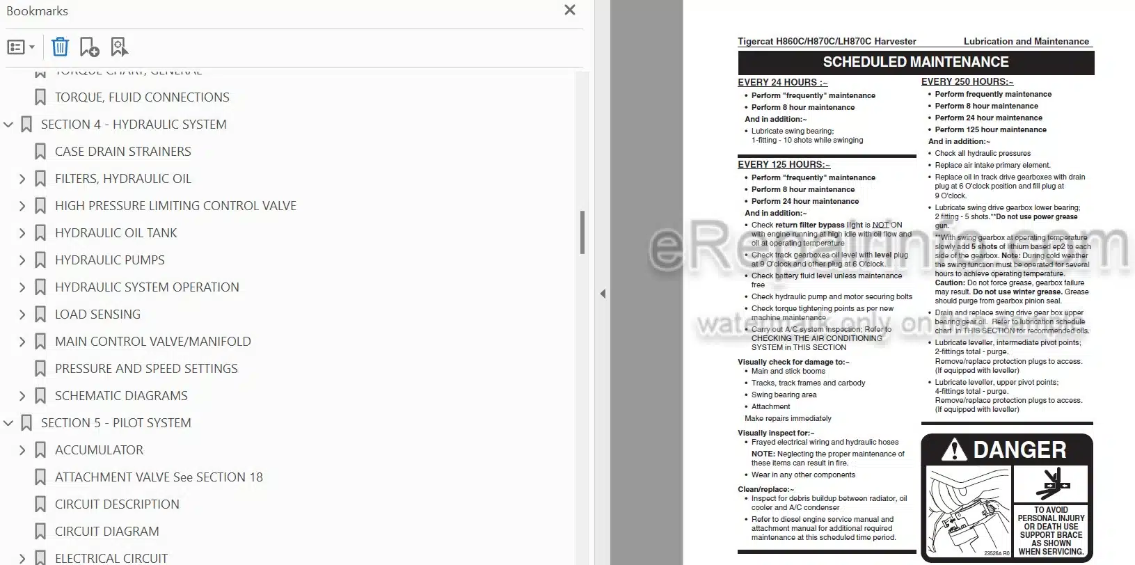
Bookmarks
Searchable
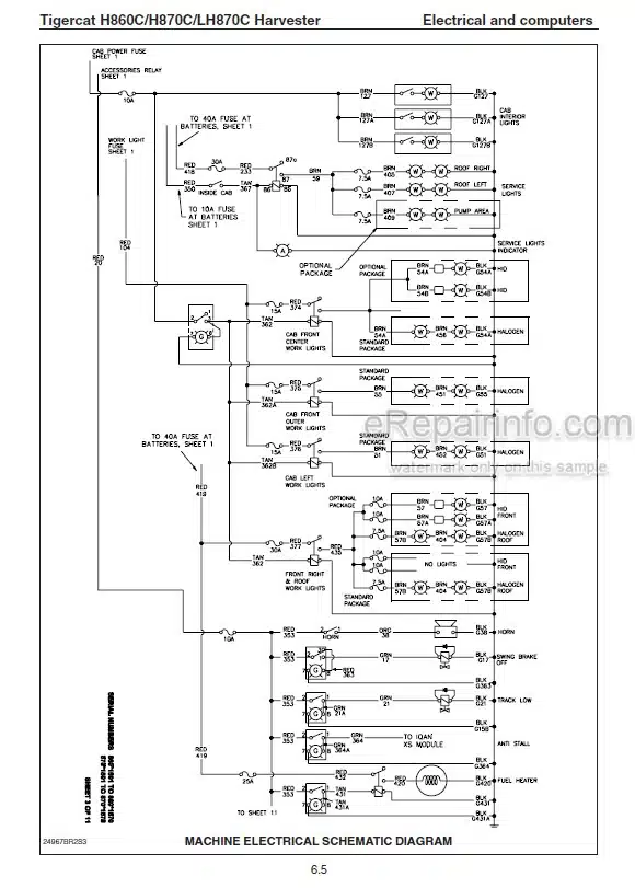
Wiring Diagrams
Hydraulic Diagrams
Model
Tigercat Harvester
H860C
H870C
LH870C
Contents
INTRODUCTION
NON-APPROVED FIELD PRODUCT CHANGES
-SAFETY
Battery Safety
Cab Exits
Cooling System
Emergency Cab Exits
Engine Doors
ER Boom System Precautions
Exhaust Fumes
Fire Prevention
Fluid Leaks
Harvesting Attachment – General Safety
Hazard Zone
Hydraulic Pressure Hazard
Loose Clothing Hazard
Machine Stability And Traction
Parking The Machine
Protective Clothing
Safety Interlock Switches On Cab Doors
Safety Precautions, General
Safety Precautions, Operating
Safety Precautions, Servicing
Safety Symbols
Signal Words
Welding, Prior To
Working With Oil
-LUBRICATION & MAINTENANCE
Air Conditioning, Checking The System
Air Intake Maintenance
Approved Hydraulic Oils
Case Drain Strainers
Checking The Air Conditioning System
Emergency Exits, Check Monthly
Engine Air Cleaner Maintenance
ER Boom System
Filter And Lubrication Schedule
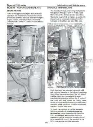
Filters
Fire Prevention
Fuel Tank Shut-Off Valves
General Maintenance
Hydraulic Oil Filters
Hydraulic Oils, Approved
Lubrication Points Diagram, Leveller
Lubrication Schedule
New Machine Maintenance
Oil Lost From Leakage
Pressure And Speed Settings
Pressure Setting Procedures
Preventive Maintenance Schedule
Scheduled Maintenance
Swing Drive Lubrication
Torque Chart. General
Torque, Fluid Connections
-HYDRAULIC SYSTEM
Case Drain Strainers
Filters, Hydraulic Oil
High Pressure Limiting Control Valve
Hydraulic Oil Tank
Hydraulic Pumps
Hydraulic System Operation
Load Sensing
Main Control Valve/Manifold
Pressure And Speed Settings
Schematic Diagrams
-PILOT SYSTEM
Accumulator
Attachment Valve See Section 18
Circuit Description
Circuit Diagram
Electrical Circuit
Pilot System Components
-ELECTRICAL AND COMPUTERS
Cab Module
Channels
Computer Control System (IQAN MDM Display)
Current Out – Troubleshooting For Open Circuits
Downloading Applications From Dealer Website
Electrical Installation – Cab
Electrical Kit – Service And Diagnostics
Electrical Schematics
Engine Module
Error Messages And Alarms
Fault Codes : Error Messages
Get Application
Get Error/Event Log
Id-Tag
IQAN
IQAN Software
Main System Errors
PDA Registration
Powerview Display Module
Switch And Sensor Locations
System Fuses And Relays
Update Application
Wire Color Code Chart
-ENGINE START AND STOP
Engine, Restarting After Engine Run Out Of Fuel
Engine, Starting
Engine, Starting, Cold Weather
Engine, Stopping
Schematic Diagram
Starting Engine
-ENGINE ANTI-STALL
Electronic Engine Anti-Stall Controller(*See Note)
IQAN Anti-Stall(*See Note)
-OIL COOLER, RADIATOR, CHARGE AIR COOLER AND FAN
Charge Air Cooler
Circuit Description
Circuit Diagram
Cooling Assembly Components
Fan Drive Control Valve
Fan Drive Electrical Schematic
Fan Motor
Fan Pump
Fan Speed Checks
Hydraulic Schematic Circuits – Oil Cooler And Fan
Oil Cooler
Radiator
-TRACK DRIVE
Brake Circuit Description
Circuit Diagram, Drive System
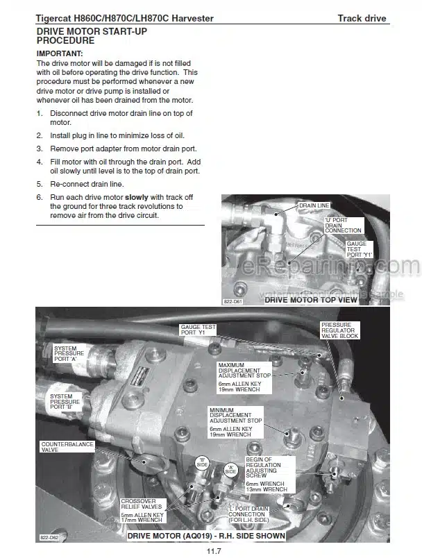
Drive Motor
Drive Motor And Gearbox Assembly
Gearbox And Drive Motor Assembly
Hydrostatic Drive System
Important Track Drive Notes
Left Track Speed Adjustment
Pressure Settings, Drive System
Right Track Speed Adjustment
Schematic Diagrams
Set Straight Travel
Track
Track Components
Track Drive Assembly
Track Speed Set-Up Procedure
Track Timing Chart
-BOOM FUNCTIONS
Adjust Oil Flow To Cylinders (Cylinder Cycle Times
Boom System Description
Circuit Diagram
Control Valve
Converting
Cylinder Cycle Times, Typical
‘ER’ Boom Manifold Connections
‘ER’ Boom System – Service Position
‘ER’ Boom System – Service Safety
‘ER’ Boom System Components
Load Sensing
Non-‘ER‘ Boom Manifold Connections
Pressure Settings, Port Relief Valves
-LEVELLING
Checking Port Relief Valves
Circuit Description
Circuit Diagram
Circuit Hydraulic Schematic
Control Valve
Counterbalance Valve
Electrical Installation (Factory Installed)
Electronic Adjustment Procedure, Levelling
Engine Anti-Stall/Load Sensing See Also Section 4
Installing A Vacuum Pump On The Hydraulic Tank
Levelling Circuit Description
Levelling Electronic Adjustment Procedure
Levelling System Description
Lubricating Cylinders And Pins See Section 3
Pressurizing The Hydraulic Tank
Replacing Port Reliefs
Set Counterbalance Valve Pressures
Undercarriage Assembly, Levelling
-SWING
Adjust Oil Flow To Swing Motor(Swing Motor Speed)
Circuit Description
Circuit Diagram
Crossline Relief Valves
Main Control Valve
Pressure Settings
Schematic Diagrams
Set Swing Motor Speed
Swing Bearing
Swing Drive Gearbox
Swing System Hydraulic Schematic
-ATTACHMENT DRIVE
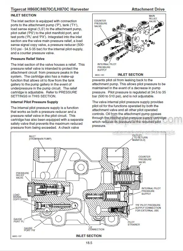
Attachment Control Valve, Pump 1
Circuit Description
Circuit Diagram
Harvesting Head Installation
Installing A Vacuum Pump On The Hydraulic Tank
Main Control Valve. Pump 2
Main Pump (Pump 2) See Section 4
Pressurizing The Hydraulic Tank
Pump 2 Electronic Adjustment Procedure
-HEAD ROTATE
Adjust Oil Flow To Head Rotate (Cycle Times)
Circuit Description
Circuit Diagram
Control Valve
Load Sensing
Pressure Settings. Port Relief Valves
Setting Cycle Times
-TELESCOPIC BOOM
Adjusting Pump 1 Feed Reduction Settings See Section 18
Attachment Control Valve
Attachment Pump See Section 18
Circuit Description
Circuit Diagram
Computer Control System (IQAN MDM Display)
Main Pump See Section 4
Replacing Main Pressure Relief Valve See Section 18
Telescopic Boom Electronic Adjustment Procedure
What you get
You will receive PDF file with high-quality manual on your email immediately after the payment.
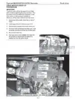

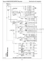
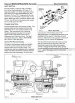
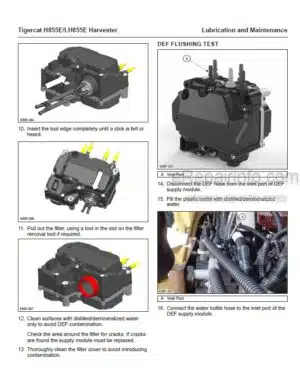
Reviews
There are no reviews yet.