


Factory Service Manual For Tigercat Track Loader. Manual Contains Illustrations, Instructions, Diagrams For Step By Step Remove And Install, Assembly And Disassembly, Service, Inspection, Repair, Troubleshooting, Tune-Ups.
Format: PDF
Language: English
Pages: 126
Number: 29313A (august 2006)
Bookmarks
Searchable
Wiring Diagrams
Hydraulic Diagrams
Model
Tigercat Track Loader
T240B
Contents
INTRODUCTION
NON-APPROVED FIELD PRODUCT CHANGES
-SAFETY
Battery Disconnect Switch
Cooling System
Exhaust Fumes
Fire Prevention
First Aid
Fluid Leaks
Loose Clothing Hazard
Protective Clothing
Safety Precautions. Operating
Safety Precautions, Servicing
Safety Symbols
Signal Words
-LUBRICATION & MAINTENANCE
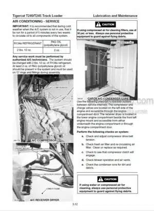
Air Conditioning – Service
Approved Hydraulic Oils
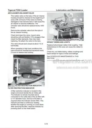
Filters
General Maintenance
Hydraulic Oil Return Filters
New Machine Maintenance
Pilot Return Pressure Filter
Pressure Settings For T240B Loader On Tracks
Preventive Maintenance Schedule
Scheduled Maintenance
Torque, Fluid Connections
Torque Settings, Recommended
Torque Specifications – General
-PILOT SYSTEM
Cab Tilt
Circuit Diagram
Electrical Circuit
Pilot System Components
Pressure Settings
-ELECTRICAL, GAUGES & ALARMS
Cab Wiring And Electrical Component Locations
Display Module
Electrical Schematic Diagram
Fuse And Relay Panel
Gauges And Alarms
Gauges And Warning Lights
Instrument Panel Wiring Diagram
Sensor Locations
Warning Lights
-ENGINE START AND STOP
Circuit Description
Engine Start Circuit
Start Circuit Diagrams
-TRACK DRIVE
Brake Release Pressure
Circuit Description
Circuit Diagram
Control Valves
Drive Motor
Drive Motor
Drive Motor And Gearbox Assembly
Gearbox And Drive Motor Assembly
Important Track Drive Notes
Pressure Settings
Pressure Settings, Drive System
Set Straight Travel
Set Track Speed
Track Components
Track Drive Assembly
Track Drive Brake Release Pressure
-BOOM
Circuit Description
Circuit Diagram
Control Valves
Filters
Hoist Valve Relief Valve Settings
Pressure Settings
Stick Valve Relief Valve Settings
-SWING
Circuit Description
Circuit Diagram
Control Valves
Gearbox, Swing Drive
Pressure Settings
Swing Motor
Swing Pump
-GRAPPLE
Circuit Description
Circuit Diagram
Grapple Connections To Boom
Grapple Control Valves
Grapple Pump
Joystick Control Valve
Pressure Settings
-DELIMBER/SLASHER
Circuit Description
Circuit Diagram
Control Valve Delimber
Control Valve Saws Retract Slasher Cut
Delimber/Slasher Circuit Description
Delimber/Slasher Pump
Electrical Circuit
Fuse And Relay Panel
Pilot Manifold
Pressure Settings
Trouble Shooting Delimber Relay Circuit
What you get
You will receive PDF file with high-quality manual on your email immediately after the payment.


Reviews
There are no reviews yet.