


Factory Service Manual For Tigercat Loader. Manual Contains Illustrations, Instructions, Diagrams For Step By Step Remove And Install, Assembly And Disassembly, Service, Inspection, Repair, Troubleshooting, Tune-Ups.
Format: PDF
Language: English
Pages: 504
Number: 46867AENG (january 2017)
Bookmarks
Searchable
Wiring Diagrams
Hydraulic Diagrams
Model
Tigercat Loader
T250D
Serial Number 250T2201–250T3000
Contents
INTRODUCTION
MACHINE IDENTIFICATION AND SERIAL NUMBERS
SAE STANDARDS FOR MACHINE OPERATOR PROTECTIVE STRUCTURES
NON-APPROVED FIELD PRODUCT CHANGES
-SAFETY
Battery Disconnect Switch
Battery Safety
Cab Exits
Cooling System
DEF (Diesel Exhaust Fluid)
Emergency Cab Exits
Engine Doors
Exhaust Fumes
Fire Prevention
Fluid Injection Injury
Fluid Leaks
Grease Injection Injury
Hydraulic Pressure Hazard
Lightening Safety Awareness
Loose Clothing Hazard
Protective Clothing
Safety Labels
Safety Precautions, General
Safety Precautions, Operating
Safety Precautions, Servicing
Safety Symbols
Signal Words
Welding, Prior To
Working With Oil
-CONTROLS AND OPERATION
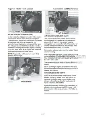
Air Cleaner
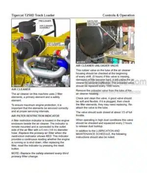
Air Cleaner Unloader Valve
Air Filter Restriction Indicator
Air Intake System
Air Precleaner
AM/FM Stereo Radio/CD
Battery Disconnect Switch
Cab Air Vents
Cab Controls
Cooler Package, Cleaning
DEF (Diesel Exhaust Fluid)
DEF Tank
Diesel Exhaust Fluid (DEF) Lb/El Messages
Diesel Exhaust Fluid (DEF) Tank
Dome Light
Emergency Stop Switch
Engine Compartment
Engine Coolant Heater Controls (Optional)
Engine Fault Code Messages-Critical
Engine, Restarting After Engine Runs Out Of Fuel
Engine Starting
Engine Stopping
Filter
Fire Extinguisher
Foot Pedal, Swing
Fuel, Refueling
Fuel Tank And Filler
Fuses And Relays
Gauges and Alarms
Heater Controls, Engine Coolant (Optional)
Horn
Hot Water Shut-Off Valve (Engine)
Hydraulic Oil
Hydraulic Pilot Filter
Hydraulic Return Filters
Interlock Limit Switch
Lights-Service Light Switch
Lights-Work Light Switch
Machine Operation
Machine Preparation
Md3 Computer
Md3 Computer And Display
Md3 Computer Main Menu
Pictograms
Precleaner, Air,
Pre-Start Checks
Refueling
Seat
Sliding Windows
Starting The Engine
Stopping The Engine
Strainer Case Drain
Switch
Tank, DEF
Tank, Hydraulic Oil
USB Port-Md3 Computer
Vacuum Switch, Hydraulic Tank
Wait To Start
Windows
Windshield Washer Fluid Reservoir
-LUBRICATION AND MAINTENANCE
After Treatment System
Aftertreatment System
Air Cleaner
Air Conditioning
Air Intake System
Air Intake Tubing And Joints
Air Precleaner
Approved Hydraulic Oils
Case Drain Strainer
Commercial Wood-Weights
Cooler Package, Cleaning
DEF (Diesel Exhaust Fluid)
Filters
Fire Prevention
Fuel Filter / Water Separator
Fuel, Refuelling
Fuel Tank
Fuel Tank And Filler
Hand Fill Pump
Hydraulic Oil
Hydraulic Oil Return Filters
Hydraulic Tank Vacuum System
Lubrication And Service Points
New Machine Maintenance
Oil Lost From Leakage
Oil Sample Collection Procedures
Oil Sampling Program
Pilot Pressure Filter
Pressure And Speed Settings
Preventive Maintenance Schedule
Refrigerant
Refuelling
Rotary Manifold Lubrication
Scheduled Maintenance
Service And Lubrication Points
Strainer Case Drain
Swing Drive Lubrication
Torque Chart, General
Torque, Fluid Connections
Torque Settings, Recommended
Vacuum System, Hydraulic Tank
Weights Of Commercial Wood
Wood, Weights Of Commercial Wood
-HYDRAULIC SYSTEM
Circuit Diagram
Controls Description
Control Valve
Control Valves
Foot Pedals And Joysticks
Hydraulic Joysticks And Foot Pedals
Hydraulic Oil Tank
Hydraulic System Operation
Joysticks and Foot Pedals
Load Sensing
Pumps, Hydraulic
Schematics
-PILOT SYSTEM
Electrical Circuit Diagram
Hydraulic Circuit Diagram
Hydraulic Schematic
Pilot System Components
Pressure Settings
-ELECTRICAL SYSTEM AND COMPUTER
Battery Disconnect-Switch
Channels
Computer
Connect To The Md3 With IQANRUN3
Downloading Applications From Dealer Website
Electrical Kit-Service And Diagnostics
Electrical Schematics
Electrical System
Fuses And Relays
Gauges And Alarms
IQANRUN 3
IQAN Software
Md3 Computer Main Menu
Relays And Fuses
Servicing The Md3 Computer With IQANRUN 3
Update Application
-ENGINE AND ANTI-STALL
Anti-Stall
Electrical Schematics
Emergency Stop Circuit
Emergency Stop Switch
Engine Start Circuit
-COOLING SYSTEM
Charge Air Cooler
Cooler Package
Cooling System
Engine Belts
Oil Cooler
-TRACK DRIVE
Circuit Diagrams
Drive Motor Crossover Relief Valves
Drive Motor Description
Drive Motor Start-Up Procedure
Hydraulic Schematics
Hydrostatic Drive System
Important Track Drive Notes
Rotary Manifold
Set Begin Of Regulation
Set Brake Release Pressure
Set Straight Travel
Summary Of Track Speed Adjustment Procedure
Track
Track Components
Track Drive Undercarriage
Track Speed Set-Up Procedure
-BOOM
Adjust Oil Flow To Cylinders (Cylinder Cycle Times)
Boom Hydraulic Circuit Diagram
Boom System Components
Boom Valve Spool Sections (Joysticks)
Cylinder Cycle Times, Typical
Hoist Valve Relief Valve Settings
Pressure Settings
-SWING
Circuit Description
Electronic Adjustment Procedure
Electronic Settings Description
Foot Pedals Pressure Settings
Hydrostatic Drive Motor
Lens Plate Timing Adjustment
Pressure Settings
Swing System Components
-GRAPPLE
Adjust Oil Flow To Grapple Open/Close-Foot Swing Only (Cylinder Cycle Times)
Adjust Oil Flow To Grapple Rotate-Foot Swing Only (Cylinder Cycle Times)
Electronic Adjustment Procedure
Grapple Options
Grapple System
Grapple System Components
Pressure Settings
Pressure Settings, Port Relief Valves
-LIVE HEEL OR TILT
Adjust Oil Flow To Cylinders (Cylinder Cycle Times)
Boom System Components
Cylinder Cycle Times, Typical
Electro-Hydraulic Circuit Diagrams
Electronic Adjustment Procedure
Live Heel/Tilt Circuit Description
Live Heel/Tilt System Components
Pressure Settings
Pressure Settings, Port Relief Valves
-DELIMBER/SLASHER
Auxiliary Control Valve
Circuit Description
Delimber/Slasher Components
Delimber/Slasher System
Diagrams/Schematics
Pressure Settings
What you get
You will receive PDF file with high-quality manual on your email immediately after the payment.


Reviews
There are no reviews yet.