


Factory Service Manual For Tigercat Trencher. Manual Contains Illustrations, Instructions, Diagrams For Step By Step Remove And Install, Assembly And Disassembly, Service, Inspection, Repair, Troubleshooting, Tune-Ups.
Format: PDF
Language: English
Pages: 492
Number: 45910AENG (april 2020)
Bookmarks
Searchable
Wiring Diagrams
Hydraulic Diagrams
Model
Tigercat Trencher
T726G
Serial Number 726T0501–726T0600
Contents
-INTRODUCTION
Machine Identification And Serial Numbers
Standards For Machine Operator Protective Structures
Non-Approved Field Product Changes
-SAFETY
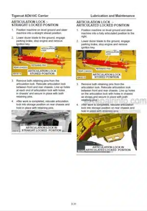
Articulation Lock Bar
Avoid Injury From Backover Accidents
Battery Disconnect Switch
Battery Safety
Boom Cylinder Lock
Cab Exits
Cooling System
Diesel Exhaust Fluid (DEF)
Exhaust Fumes
Fire Prevention
Fluid Injection Injury
General Safety Precautions
Grease Injection Injury
Interlock Door Switches
Lightning Safety Awareness
Machine Stability And Traction
Notice Labels
Operating Safety Precautions
Parking The Machine
Pilot System Pressure, Release
Preparing The Machine For Maintenance
Protective Clothing
Release Pilot System Pressure
Safety Hazards
Safety Labels
Safety Precautions
Safety Signal Words
Safety Symbols
Servicing Safety Precautions
Transporting The Machine
Trenching Operation Safety
Welding, Prior To
Working With Oil
-CONTROLS AND OPERATION
Air Compressor–Air Supply
Air Conditioning Controls
Air Vents, Cab
Alarm
Alarm Light
Audio System
Auxiliary Power Supply, 12 Volt
Battery Boosting
Battery Disconnect Switch
Bluetooth Functions
Brakes
Camera And Monitor
Cigar/Cigarette Lighter
Cold Weather Starting
Computer
Computer And Display
Controls-Cab
Coolant Heater, Engine (Optional)
Diagnostics Connection, Engine
Drive Control
Eco Mode
Engine
Engine Coolant Heater (Optional)
Engine, Restarting After Engine Runs Out Of Fuel
Fan Switch (Engine Cooling)
Filters
Fire Detection System
Fire Extinguisher
Foot Pedal Controls
Fuel Heater
Head Tilt
Heater, Engine Coolant (Optional)
Horn
Ignition Key Switch
Instrument Panel
Interior Cab Light Switch
Interlock Reset Switch
Joysticks
Lighter, 24 Volt
Lights
Machine Preparation
Mirror, Rearview
Operating Machine
Parking Brake Switch
Pictograms
Prestart Checks
Rear View Mirror
Refuelling
Seat
Speed/Direction Control
Starting Engine
Steering Column
Stopping Engine
Switches
USB Port
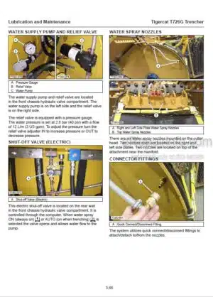
Water Spray
-LUBRICATION AND MAINTENANCE
Access Doors And Covers
Aftertreatment System (Tier 4F Machines Only)
Air Conditioning System
Air Intake System
Anti-Corrosion Spray, Removal
Approved Hydraulic Oils
Articulation Lock Bar Installation
Axle Lubrication
Battery Care
Belt, Serpentine
Brake, Parking
Care Of Polycarbonate Windows
Care Of The Machine
Case Drain Strainer
Center Joint
Center Joint Lock Pin
Cleaning Cooler Package
Diagnostics Connection
Diesel Exhaust Fluid (DEF) (Tier 4F Machines Only)
Diesel Exhaust Fluid Tank
Driveshafts
Drum Water Spray System
Emergency Exits
Engine Access Panels
Engine Air Precleaner
Engine Diagnostics Connection
Filters
Fire Prevention
Fluid Analysis Program
Fluid Sampling Program
Fuel, Refuelling
Fuel Tank
Fuses And Relays
Graffiti Removal
Heater, Fuel
Hydraulic Oil Operating Range Chart
Hydraulic System
New Machine Maintenance
Parking Brake
Pressure And Speed Settings
Pressure Washing
Preventive Maintenance Schedule
Pump Drive Gearbox
Refilling The Hydraulic System
Refrigerant Specification
Refuelling Procedure
Scheduled Maintenance
Service And Lubrication Points
Startup Procedure After Major Machine Maintenance
Strainers
Tire Pressures
Torque Chart, General
Torque Chart, Specific
Torque, Fluid Connections
Towing Instructions
Transmission
Windows
-HYDRAULIC SYSTEM
Boom Valve
Electrical Components
Electrical Schematic-XA2-A0 Module
Electrical Schematic-XA2-A1 Module
Gauge Fittings-Test Ports
Hydraulic Oil Heating Procedure
Hydraulic System Circuits
Pilot Manifold
Port Reliefs
Pumps
Safety Precautions
-PILOT SYSTEM
Accumulator Charge Valve
Accumulators
Circuit Components-Pilot Functions
Circuit Components-Pilot Supply
Circuit Description
Circuit Schematic-Pilot Functions
Circuit Schematic-Pilot Supply
General Description
Interlock System
Pilot Manifold
Pressure Settings
Release Pilot System Pressure
Safety Precautions
-ELECTRICAL AND COMPUTERS
Aftertreatment System Sensors and Electrical Components
Cab Electrical Components
Channels
Chassis Sensors And Electrical Components
Communication Cable
Computer And Display Module
Computer Control System
Electrical Kit-Service And Diagnostics
Electrical Schematic
Electrical System
Engine Diagnostics Connection
Engine Electrical Components
Fuses And Relays
IQAN Program Software
Machine Program Updates
XA2 Modules
-ENGINE
Engine
Pump Drive Gearbox
Start Circuit
-DRIVE
Axles
Circuit Components
Circuit Schematic
Drive Configuration
Drive Motors
Drive Pump
Driveshafts
Hydrostatic Drive System
Pressure Settings
Right Drive Motor Minimum Displacement
Safety Precautions
Transmission
Wheel Installation
-BRAKES
Brake Accumulator
Brake Pedal/Brake Pilot Valve
Brakes
Parking Brake
-COOLING SYSTEM
A/C Condenser
Aftertreatment System Cooling
Charge Air Cooler (CAC)
Cooler Package
Cooling Fan
Engine Coolant Heater (Optional)
Hydraulic Oil Cooler
Pump Drive Gearbox Cooler
Radiator
-STEERING AND CENTER JOINT
Boom/Fan/Steer Pump
Center Joint
Circuit Components
Circuit Description
Circuit Schematic
Pressure Settings
Priority Valve
Safety Precautions
Steering Wheel
Steer Relief Valve
Steer Valve
-LIFT BOOM
Boom Valve
Circuit Components
Circuit Description
Circuit Schematic
Joystick-Right
Pressure Settings
Safety Precautions
-TILT
Boom Valve
Circuit Components
Circuit Description
Circuit Schematic
Joystick-Right
Pressure Settings
Safety Precautions
-ATTACHMENT DRIVE
Attachment Pump
Circuit Components
Circuit Description
Circuit Schematic
Electrical Circuit
Pressure Settings
Safety Precautions
-HYDRAULIC SIDE PLATE SHIFT
Boom Valve
Circuit Components
Circuit Description
Circuit Schematic
Joystick-Right
Pressure Settings
Safety Precautions
-COMPRESSED AIR SYSTEM
Components
Overview
ELECTRICAL SCHEMATIC
HYDRAULIC SCHEMATIC
What you get
You will receive PDF file with high-quality manual on your email immediately after the payment.


Reviews
There are no reviews yet.