


Factory Repair Manual For Toyota Forklift. Manual Contains Illustrations, Instructions, Diagrams For Step By Step Remove And Install, Assembly And Disassembly, Service, Inspection, Repair, Troubleshooting, Tune-Ups.
Format: PDF
Language: English
Pages: 696
Number: CE370-1 (november 2016)
Bookmarks
Searchable
Wiring Diagrams
Hydraulic Diagrams
Model
Toyota Forklift
8FBMT40
8FBMT45
8FBMT50
Contents
INDEX
-GENERAL
Vehicle Exterior View
Vehicle Models
Chassis Number
How To Use This Manual
Operating Tips
List Of Suspension Rope Angles
Safety Load For Each Suspension Rope Angle
Component Weights
Towing The Truck
Electrical Components Inspection
Notes On SAS
Tightening Torque Table
Table Of Lubricants And Fluids
Periodic Maintenance
-BATTERY
Battery Compartment And Required Weight
Standard Service Values
Multi-Display Functions
State Of Battery Charge Indicator
Procedure Set Temperature Sensor Battery
Battery Management Parameters
Table Of BDI Max, BDI Min, Reset Volt Values
Battery Indicator Troubleshooting
Troubleshooting
Battery Unit
Inspection
State Of Battery Charge
Battery Capacity
Gel Batteries
Replacing Battery Plug Terminals
-CONTROL SYSTEM
General
Can-Bus Connection
Rear Compartment Fuses
Fuses Under Dashboard
Contactors
DC/DC Converters
Logic Units
Contactor Group
MCB Card
Multi-Display Functions
24-12 V Fuse Card
Armrest Card
Armrest Card Potentiometers
Accelerator Potentiometer
Steering Potentiometer
Tilt Angle Potentiometer
Mast Pressure Sensor
Mast Height Switch
Yaw Rate Sensor
Calibrations
-MULTI-FUNCTION DISPLAY
General
Menu Map
Operator Menu
Administrator Menu
Administrator Menu Screen (With Vehicle Startup Using Key)
Administrator Menu Screen (With Vehicle Startup Using Pin Code Via Keypad)
Mask Menu
Analyzer
Tuning
Option Set
Matching
Others Menu
-TROUBLESHOOTING
Connector Check
Wire Harness And Connectors Inspection Procedure
Insulation Check Procedure
Motor Winding Check Procedure
Temperature Sensor Check Procedure
Can-Bus Check Procedure
Diagnostic Codes List
When An Error Code Is Displayed
-MOTOR
Sensor
Pump Motor
-DRIVE UNIT & FRONT AXLE
General
Components – Standard Version
Components – Negative Brake Version
Front Axle Assembly
Maintenance
-REAR AXLE
Rear Axle Assembly
Rear Axle
Rear Axle Hub – Cast Articulated Joint
Rear Axle Cylinder
-STEERING
Scraper
Steering Column
Orbitrol
Troubleshooting
-BRAKE
General
Specifications
Components
Brake Unit
Parking Brake
Negative Brake Version
-BODY
Components
Operator’s Seat
Battery Cover Unit
Overhead Guard
Counterweight
Rear Chassis
-MATERIAL HANDLING SYSTEM
Hydraulic Circuit
Negative Brake Hydraulic Diagram
Components
Oil Tank
Oil Filter And Air Breather Pipe
Hydraulic Oil
Lifting Load Down Test
Natural Forward Tilting Test
Oil Leak Test
-MAST
Mast
Fork Carriage Assembly And Mast Removal
Mast Assembly
Mast Group
Lifting Bracket
Replacing The Fork Carriage Guide Pads
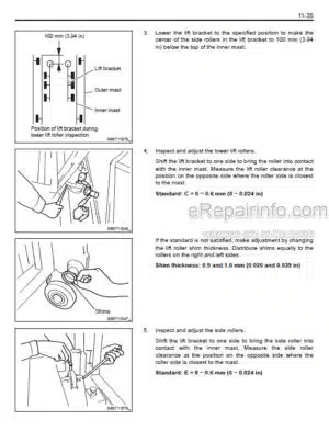
Adjusting The Mast
Standard For Selecting An Oversize Roller
Mast Roller
Chains
Fork
Adjusting The Adjusting Rings On The Lift Cylinder Rod (To Avoid Irregular Lifting)
-CYLINDER
Lifting Cylinders
Tilting Cylinders
-OIL PUMP
Scraper
Components
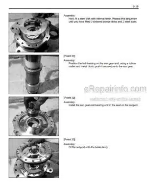
Disassembly-Assembly
-OIL CONTROL VALVE
Hydraulic Diagram
Components
Specifications
Disassembly-Assembly
Maximum Pressure Adjustment
-SAS FUNCTION
General
For Repair Work
Hand Grip Position Correction Valve
Steering Potentiometer
Tilt Angle Potentiometer
Mast Pressure Sensor
Mast Height Switch
Yaw Rate Sensor
Oscillation Lock Cylinder
Adjustment
-MAIN OPTIONS
DC/DC Converters
Rear Compartment Fuses
Fuses Under Dashboard
Height Selector
Bump Sensor – DHU – Keypad
Flash – Rotating Lamp
Work Spotlights
Combined Lights
Heater – Heated Rear Window
Windscreen Wipers – Radio – Cab Light
-APPENDIX
Components
Wiring Diagram
Wiring
What you get
You will receive PDF file with high-quality manual on your email immediately after the payment.


Reviews
There are no reviews yet