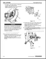
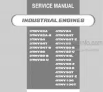
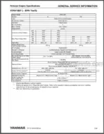
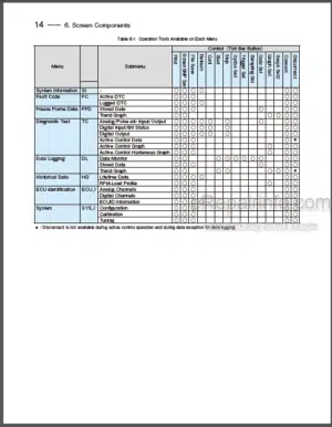
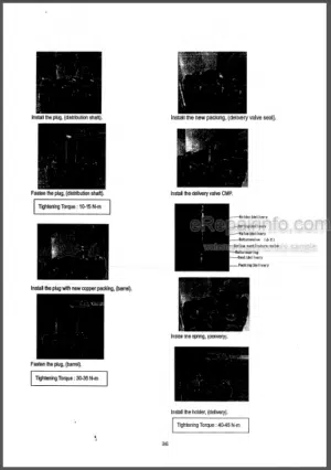
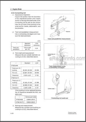
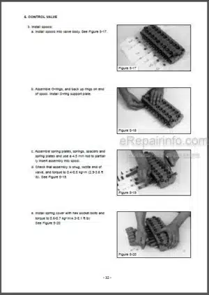
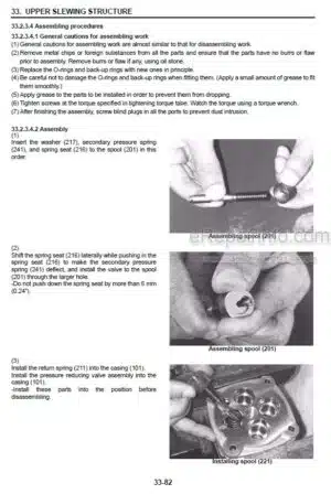
Factory Service Manual For Yanmar TNV82A To 3TNV88U 4TNV84 To 4TNV106T Industrial Engine. Tons of illustrations, instructions, diagrams for step by step remove and install, assembly and disassembly, service, inspection, repair, troubleshooting, tune-ups.
Format: PDF
Language: English
Pages: 378
Bookmarks: Yes
Model
Yanmar 3TNV82A, 3TNV82A-B, 3TNV84, 3TNV84T, 3TNV84T-B, 3TNV88, 3TNV88-B, 3TNV88-U,4TNV84, 4TNV84T, 4TNV84T-Z, 4TNV88, 4TNV88-B, 4TNV88-U, 4TNV94L, 4TNV98, 4TNV98-Z, 4TNV98E, 4TNV98T, 4TNV98T-Z, 4TNV106, 4TNV1O6T
Contents
INTRODUCTION
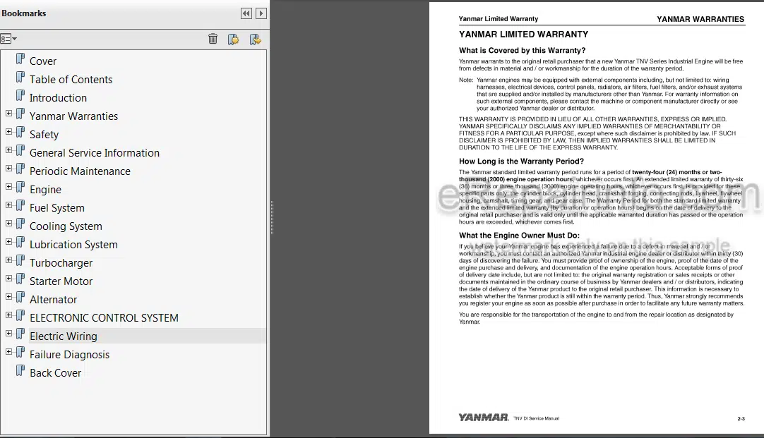
-YANMAR WARRANTIES
–Yanmar Limited Warranty
What is Covered by this Warranty
How Long is the Warranty Period
What the Engine Owner Must Do
To Locate an Authorized Yanmar Industrial Engine Dealer or Distributor
What Yanmar Will Do
What is Not Covered by this Warranty
Warranty Limitations:
Warranty Modifications
Questions:
Retail Purchaser Registration
–Emission System Warranty
–Yanmar Co, Ltd Limited Emission Control System Warranty – USA Only
Your Warranty Rights and Obligations
Manufacturer’s Warranty Period
Warranty Coverage
Warranted Parts
Exclusions
Owner’s Warranty Responsibilities
-SAFETY
Safety Statements
Safety Precautions
-GENERAL SERVICE INFORMATION
Component Identification
Location of Labels
Engine Nameplate (Typical)
Emission Control Regulations
EPA/ARB Regulations – USA Only
Emission Control Labels
The 97/68/EC Directive Certified Engines
Engine Family
Function of Major Engine Components
–MAIN ELECTRONIC CONTROL COMPONENTS AND FEATURES
Function of Cooling System Components
Diesel Fuel
Diesel Fuel Specifications
Filling The Fuel Tank
Priming the Fuel System
Engine Oil
Engine Oil Specifications
Engine Oil Viscosity
Checking Engine Oil
Adding Engine Oil
Engine Oil Capacity (Typical)
Engine Coolant
Engine Coolant Specifications
Filling Radiator with Engine Coolant
Engine Coolant Capacity (Typical)
—Specifications
Description Of Model Number
Engine Speed Specifications
Engine General Specifications
Principal Engine Specifications
3Tnv82A (Epatier2)
3Tnv84 (Epa Tier2)
3Tnv84T (Epa Tiei2)
3Tnv88 (Epa Tier2)
4Tnv84 (Epa Tier2)
4Tnv84T (Epa Tier2)
4Tnv88 (Epa Tier2)
4Tnv94L (Epa Tier2)
4Tnv98 (Epa Tier2)
4Tnv98T (Epa Tier2)
4Tnv106(Epa Tier2)
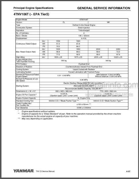
4Tnv106T (Epa Tier2)
3Tnv82A-B (Complies With Epa Interim Tier4)
3Tnv84T-Z (Complies With Epa Interim Tier4)
3Tnv84T-B (Complies With Epa Interim Tier4)
3Tnv88-Z (Complies With Epa Interim Tier4)
3Tnv88-U (Complies With Epa Interim Tier4)
3Tnv88-B (Complies With Epa Interim Tier4)
4Tnv84T-B 4Tnv84T-Z (Complies With Epa Interim Tier4)
4Tnv88-Z (Complies With Epa Interim Tier4)
4Tnv88-U (Complies With Epa Interim Tier4)
4Tnv88-B (Complies With Epa Interim Tier4)
4Tnv98-E (Complies With Epa Interim Tier4)
4Tnv98-Z (Complies With Epa Interim Tier4)
4Tnv98T-Z (Complies With Epa Interim Tier4)
Engine Service Standards
Tightening Torques for Standard Bolts and Nuts
—Abbreviations and Symbols
Abbreviations
Symbols
—Unit Conversions
Unit Prefixes
Units of Length
Units of Volume
Units of Mass
Units of Force
Units of Torque
Units of Pressure
Units of Power
Units of Temperature
-PERIODIC MAINTENANCE
Before You Begin Servicing
—Introduction
The Importance of Periodic Maintenance
Performing Periodic Maintenance
Yanmar Replacement Parts
Required EPA / ARB Maintenance -USA Only
EPA / ARB Installation Requirements – USA Only
—Periodic Maintenance Schedule
—Periodic Maintenance Procedures
After Initial 50 Hours of Operation
Every 50 Hours of Operation
Every 250 Hours of Operation
Every 500 Hours of Operation
Every 1000 Hours of Operation
Every 1500 Hours of Operation
Every 2000 Hours of Operation
Every 3000 Hours of Operation
-ENGINE
Before You Begin Servicing
Introduction
—Cylinder Head Specifications
Adjustment Specifications
Cylinder Head
Intake I Exhaust Valve and Guide
Push Rod
Rocker Ann and Shaft
Valve Spring
—Camshaft and Timing Gear Train Specifications
Camshaft
Idler Gear Shaft and Bushing
Timing Gear Backlash
—Crankshaft and Piston Specifications
Crankshaft
Thrust Bearing
Piston
Piston Ring
Connecting Rod
Tappet
—Cylinder Block Specifications
Cylinder Block
—Special Torque Chart
Torque for Bolts and Nuts
Special Service Tools
Measuring Instruments
2-Valve Cylinder Head
2-Valve Cylinder Head Components
Components Of A Two-Valve Cylinder Head
Disassembly Of 2-Valve Cylinder Head
Cleaning Of Cylinder Head Components
Inspection Of Cylinder Head Components
Reassembly Of Cylinder Head
—4-Valve Cylinder Head
4-Valve Cylinder Head Components
Disassembly Of 4-Valve Cylinder Head
Cleaning Of Cylinder Head Components
Inspection Of Cylinder Head Components
Reassembly Of Cylinder Head
—Measuring And Adjusting Valve Clearance
2-Valve Cylinder Heads
4-Valve Cylinder Heads
—Crankshaft And Camshaft Components
Disassembly Of Engine
Disassembly Of Camshaft And Timing Components
Disassembly Of Crankshaft And Piston Components
Inspection Of Crankshaft And Camshaft Components
Honing And Boring
Reassembly Of Crankshaft And Piston Components
Reassembly Of Camshaft And Timing Components
Final Reassembly Of Engine
—Egr System
Egr System
Egr System
Inspectingfcleaning Egr Related Components
-FUEL SYSTEM
Before You Begin Servicing
—introduction
Fuel Injection Pump
Stop Solenoid
Cold Start Device
Trochoid Fuel Pump
Electronically controlled governor
—Fuel System Specifications
Special Torque Chart
Test and Adjustment Specifications
—Special Service Tools
—Measuring Instruments
—Fuel System Diagram
—Fuel System Components
2-Valve Cylinder Head
4-Valve Cylinder Head
—Fuel Injection Pump
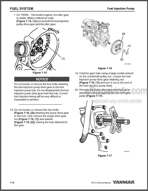
Removal of Fuel Injection Pump
Installation of Fuel Injection Pump
—Idle Sub Spring Adjustment
—Checking and Adjusting Fuel Injection Timing
Determining the Fuel Injection Timing Specification
Checking Fuel Injection Timing
Adjusting Fuel Injection Timing
—Fuel Injectors
Removal of Fuel Injectors
Testing of Fuel Injectors
Disassembly and Inspection of Fuel Injectors
Adjusting Fuel Injector Pressure
Reassembly of Fuel Injectors
Installation of the Fuel Injectors
-COOLING SYSTEM
Before You Begin Servicing
Introduction
Cooling System Diagram
Engine Coolant Pump Components
Engine Coolant System Check
—Engine Coolant Pump
Removal of Engine Coolant Pump
Disassembly of Engine Coolant Pump
Cleaning and Inspection
Reassembly of Engine Coolant Pump
Installation of Engine Coolant Pump
-LUBRICATION SYSTEM
Before You Begin Servicing
Introduction
Oil Pump Service Information
Lubrication System Diagram
Checking Engine Oil Pressure
—Trochoid Oil Pump
3TNV82A to 4TNV88 Oil Pump Components
Disassembly of Oil Pump
Cleaning and Inspection
Reassembly of Oil Pump
—Trochoid Oil Pump
3TNV82A-B 3TNV88-8, 3TNV88-U, 4TNV88-B4TNV88-U 3TNV84T-Z 4TNV84T-Z Oil Pump Components
Disassembly of Oil Pump
Cleaning and inspection
Reassembly of Oil Pump
—Trochoid Oil Pump
4TNV94L/98/106 Oil Pump Components
Disassembly of Oil Pump
Cleaning and Inspection
Reassembly of Oil Pump
-TURBOCHARGER
Before You Begin Servicing
Introduction
—Specifications
Turbocharger Service Information
—Troubleshooting
Excessive Exhaust Smoke
Generates White Smoke
Sudden Oil Decrease
Decrease in Output
Poor (Slow) Response (Starting) of Turbocharger
Abnormal Sound or Vibration
—Turbocharger Components
—Turbocharger Component Functions
Theory of Operation
Compressor Side Sealing Mechanism
Waste Gate Modulation
—Washing Procedure
—Periodic Inspection
Visual Inspection
Inspection of Rotor Rotation
Inspection of Rotor Play
Removal of Turbocharger
Checking Rotor Play
Waste Gate Valve Test
Waste Gate Actuator Leak Test
Installation of Turbocharger
-STARTER MOTOR
8efore You Begin Servicing
introduction
Starter Motor Information-3TNV82A to 4TNV88 – Standard and Optional
Starter Motor Specifications
Starter Motor Troubleshooting
Starter Motor Components
—Starter Motor
Removal of Starter Motor
Disassembly of Starter Motor
Cleaning and Inspection
Reassembly of Starter Motor
Check Pinion Projection Length
No-Load Test
Installation of Starter Motor
-ALTERNATOR
Before You Begin Servicing
introduction
Dynamo and Alternator Information
3TNV82A to 4TNV106T – Standard and Optional Dynamos-3TNV82A to4TNV106T – Standard and Optional Alternators
Alternator Specifications
Dynamo Specifications
Alternator T roubleshooting
Alternator Components
Alternator Wiring Diagram
Alternator Standard Output
—Alternator
Removal of Alternator
Disassembly of Alternator
Reassembly of Alternator
Installation of Alternator
—Dynamo Component Location
—Dynamo Wiring Diagram
—Operation of Dynamo
—Dynamo Standard Output
—Testing of Dynamo
Testing Stator Coil Continuity
Testing Stator Coil Short-to-Ground
Testing Dynamo Regulated Output
-ELECTRONIC CONTROL SYSTEM
Engines Available With The Electronic Control System
8Efore You 8Egin Servicing
Introduction
Electronic Control System
Electronic Control Harness Connections
-ELECTRIC WIRING
Electric Wiring Precautions
Electrical Wire Resistance
Battery Cable Resistance
Electrical Wire Sizes – Voltage Drop
Conversion of AWG to European Standards
-FAILURE DIAGNOSIS
Special Service Tools
Troubleshooting By Measuring Compression Pressure
Compression Pressure Measurement Method
Quick Reference Table For Troubleshooting
What you get
You will receive PDF file with high-quality manual on your email immediately after the payment.

Reviews
There are no reviews yet.