


Factory Service Manual For Bomag Sanitary Landfill And Fast Moving Soil Compactor. Manual Contains Illustrations, Instructions, Diagrams For Step By Step Remove And Install, Assembly And Disassembly, Service, Inspection, Repair, Troubleshooting, Tune-Ups.
Format: PDF
Language: ENG
Pages: 782
Number: 00892355 (september 2013)
Bookmarks: Yes
Searchable: Yes
Wiring Diagrams: Yes
Hydraulic Diagrams: Yes
Model
Bomag Sanitary Landfill Compactor And Fast Moving Soil Compactor
BC462RB
BC472RB
BC472RS
BC462EB
S/N 10193003 ….
S/N 10193000 ….
S/N 10193001 ….
S/N 10193002 ….
Contents
-GENERAL
Introduction
Safety Regulations
General Repair Instructions
Tightening Torques
-EARTH COMPACTOR – REFUSE COMPACTOR
Refuse Compactor – Earth Compactor
-TECHNICAL DATA
Technical Data
-MAINTENANCE
General Notes On Maintenance
Fuels And Lubricants
Table Of Fuels And Lubricants
Running-In Instructions
Maintenance Table
-ELECTRICS
Battery Service, Checking The Main Battery Switch
Starting The Engine With Jump Leads
Main Battery Switch
Hydraulic Oil Temperature
Pressure Switch, Hydraulic Oil Filter
Magnetic Sensor, Hydraulic Oil
Pressure Switch For Brake
Fuel Gauge
Cab Electrics
Fuses
Machine Related Electrics
-ENGINE ELECTRICS
Emr3 System Components
Pin Assignment Of Engine Control EDC16 / EMR3
Rotary Speed Sensor For Camshaft
Rotary Speed Sensor For Crankshaft
Rail Pressure Sensor
Fuel Pressure Sensor
Fuel Control Unit
Injector
Oil Pressure Sensor
Sensor For Charge Air Temperature And Charge Air Pressure
EMR Coolant Temperature Sensor
Glow Plugs
Sensor, Water In Fuel
Fuel Pre-Heating
Air Filter Vacuum Switch
Float Switch In Coolant Container
Coolant Temperature Gauge
Charge Control Light, Engine Rpm-Meter
System Faults Indicated By Flashing Code
Diagnose With Serdia
Diagnose With Can-Bus
Diagnostics Interface
Flashing Code
EMR3 List Of Fault Codes
Generator
Electric Starter
-ENGINE
Diesel Engine
Engine Description TCD 2013, 4 And 6 Cylinder, 2 Valves
Lubrication Oil Circuit TCD 2012 / 2013
Coolant Circuit TCD 2012 / 2013
Fuel System TCD 2012/2013
Deutz Common Rail (DCR) Injection System For TCD 2012 / 2013
Exhaust Gas Recirculation TCD 2012 / 2013
Engine Problems
Wastegate – Charge Pressure Controller On TCD-Engines
Adjust The Valve Clearance
Checking The Engine Oil Level
Change Engine Oil And Oil Filter Cartridge
Checking, Cleaning The Water Separator
Replacing The Fuel Pre-Filter Cartridge, Bleeding The Fuel System
Replacing The Fuel Filter Cartridges
Check The Coolant Level
Changing The Coolant
Checking The Anti-Freeze Concentration And The Condition Of The Coolant
Checking The Thermostat In Disassembled State
Checking Ribbed V-Belts And Compressor V-Belts
Replacing Ribbed V-Belt And Idler Pulley
Air Filter Maintenance
Special Tools, Deutz Engine (TCD 2013 2V)
-AIR CONDITIONING SYSTEM
Physical Basics
Refrigerant R134A
Compressor Oil / Refrigeration Oil
Working Principle Of The Air Conditioning System
Monitoring Devices
Description Of Components
Measuring The Compressor Oil Level
Checking The Magnetic Clutch
Inspection And Maintenance Work
Service The Air Conditioning
Checking Ribbed V-Belts And Compressor V-Belts
Replacing Ribbed V-Belt And Idler Pulley
Drying And Evacuation
Emptying In Case Of Repair
Leak Test
Filling Instructions
Trouble Shooting In Refrigerant Circuit, Basic Principles
Trouble Shooting, Refrigerant Circuit Diagram
Trouble Shooting Procedure
Steam Table For R134A
Module A108
-CENTRAL LUBRICATION SYSTEM
System Layout
Technical Description
Control
Lubrication Process
Progressive Distributor
Lubrication Oil Pump
Checking The Central Lubrication System, Filling Up
Faults And Causes
Fault – Cause – Remedy
Failure Of Central Lubrication System (Grease Emerges From Relief Valve)
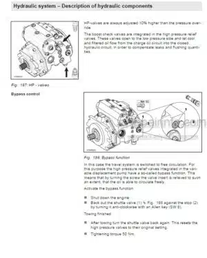
-HYDRAULICS
Hydraulic Circuit
Travel Pump A4VG110 DA
Travel Pump A4VG110 HT
Steering And Working Pump
Axial Piston Swash Plate Principle.
Troubleshooting Axial Piston Pumps
Travel Motor
Trouble Shooting, Variable Displacement Axial Piston Motor
External Gear Pumps
Travel Circuit
Towing The Machine
Checking The Oil Level In The Travel Gear
Steering And Working Hydraulics
Checking The Hydraulic Oil Level
Replace Hydraulic Oil Filter
Change Hydraulic Oil And Breather Filter
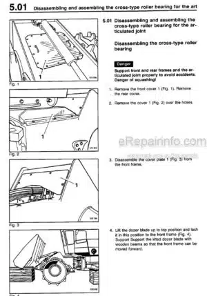
-OSCILLATING ARTICULATED JOINT
Repair Overview
Repairing The Articulated Joint
-COMPACTOR WHEELS AND DOZER BLADE
Replacing The Wheel Caps
Adjust Scrapers And Edge Cutter
Checking The Cutting Plates, Replacing The Cutting Plates If Necessary
-SUPPLIERS DOCUMENTATION
Steering And Working Pump
Wheel Drive
Travel Motor
-CIRCUIT DIAGRAMS
Hydraulic Diagram
Wiring Diagram
What you get
You will receive PDF file with high-quality manual on your email immediately after the payment.


Reviews
There are no reviews yet.